
Acoustic ash removal

Inactive Publication Date: 2014-01-09
MONSON ROBERT JAMES +2
View PDF5 Cites 8 Cited by
  • Summary
  • Abstract
  • Description
  • Claims
  • Application Information

AI Technical Summary

Benefits of technology

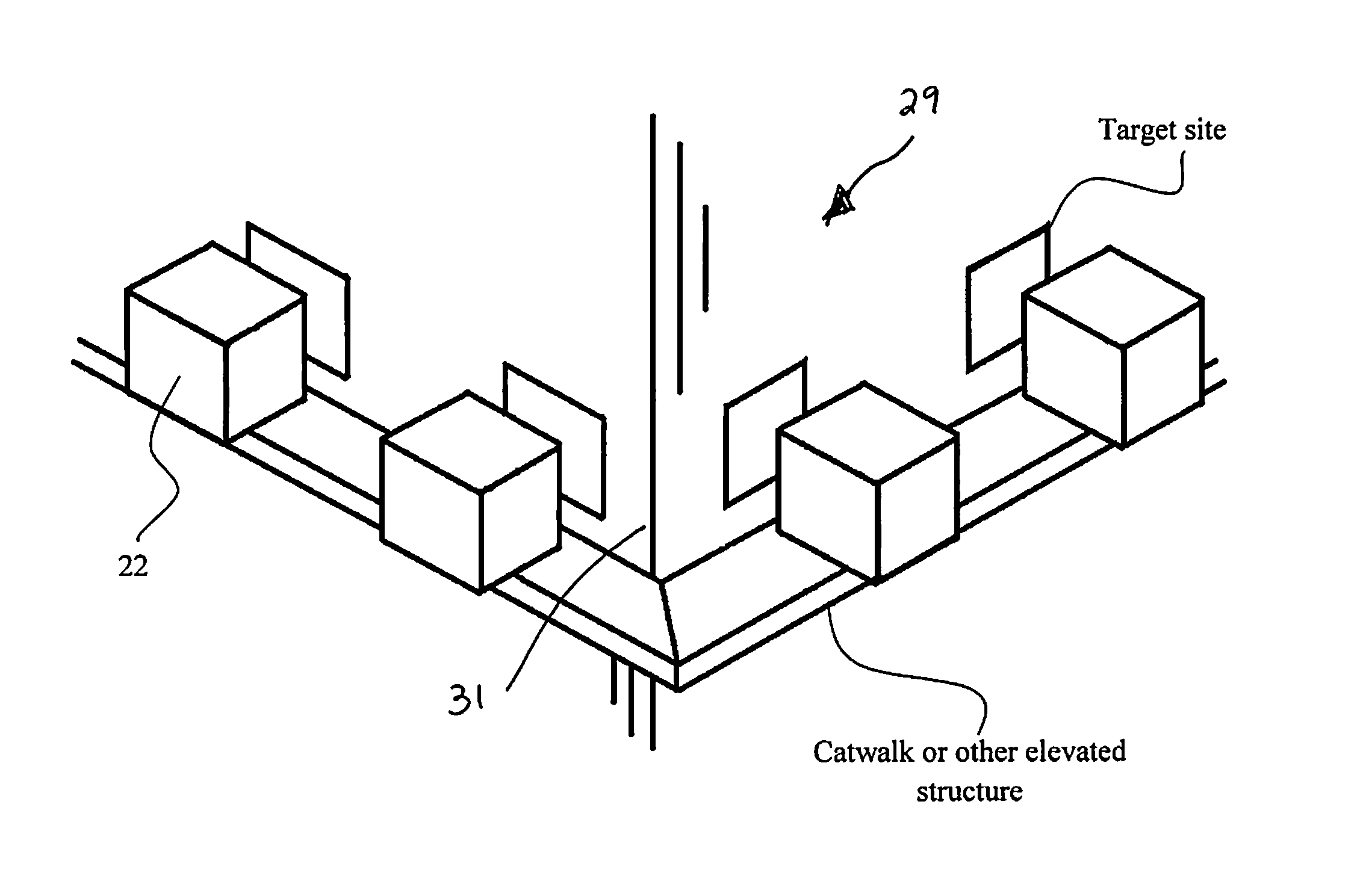
The patent describes a system for improving the longevity of speakers used in a reactor. By positioning the speakers a certain distance from the reactor, a heat dissipation zone is created that prevents the transfer of heat from the reactor to the speakers. This prevents damage to the speakers and ensures efficient operation of the reactor. The speakers can be mounted permanently at problem spots in the reactor where slag build-up is likely or heavy. The system also includes a driver housing with a hole that creates a synthetic jet of air to cool the driver assembly, increasing its longevity. Overall, the system improves the efficiency and durability of the speakers in the reactor.

Problems solved by technology

The combustion of the coal generates large quantities of ash particulates.
The oxide components produce a hard, crystalline material that adheres to the internal surfaces of the reactor and can be difficult to separate from the reactor wall or internal structures without substantial mechanical effort.
Depending on the amount of silicon oxide present, the slag can comprise a rounded, smooth texture or a sharp, pointed texture which can injure workers removing the slag.
The inherent challenge is that the reactors can be very large and are often several stories in height making manual removal of the slag tedious and time consuming.
Aside from the inherent danger of firing a projectile weapon within an enclosed space, the typically large amount of slag that must be removed requires a substantial number of shots to remove the slag creating a large quantity of shot that must also be removed.
The dissolved slag or the liquid cleaner itself can be highly toxic to the users particularly if a portion of the slag or liquid cleaner vaporizes within the reactor.
All of the approaches require shutdown of the reactor and require workers to enter the potentially toxic environment within the reactor to manually remove the slag.

Method used


Image

  • Acoustic ash removal
  • Acoustic ash removal
  • Acoustic ash removal

Examples


Embodiment Construction

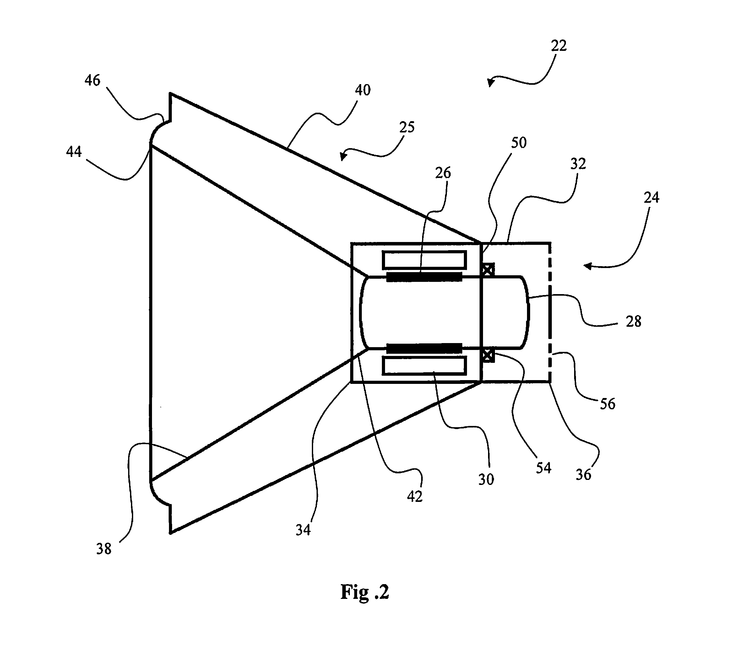
[0032]As depicted in FIG. 2, an acoustic system 20, according to an embodiment of the present invention, comprises at least one speaker 22 having a driver assembly 24 and a cone assembly 25. The driver assembly 24 further comprises a speaker coil 26, a driver 28, a permanent magnet 30 and a driver housing 32. As depicted in FIG. 2, the speaker coil 26 is arranged in a cylindrical coil around the driver 28, wherein the permanent magnet 30 comprises a cylindrical pipe shape encircling the cylindrical speaker coil 26. Alternatively, the permanent magnet 28 can comprise a cylindrical shape extending into the center of the speaker coil 26, wherein the driver 28 defines an inner cavity extending longitudinally through the speaker coil 26. The driver housing 32 comprises a cup shape having an open front end 34 and a closed rear end 36. The cone assembly 26 can comprise a cone 38 and a speaker housing 40. The cone 38 comprises a frustoconical shape having a first end 42 and a second end 44,...


PUM


Abstract

An acoustic system having a plurality of speakers applying acoustic energy as a series of acoustic waves to various target sites on the exterior of the reactor to vibrate and deflect the interior surfaces of the reactor structure such that the slag is dislodged from the internal surfaces of the reactor structure. Each speaker generates acoustic waves having a waveform corresponding to the resonant frequency of the ash crystallized on the reactor structures. The acoustic waves induce vibrations and / or deflections in the portion of the reactor wall to which the slag is engaged as well as the slag itself breaking the interstitial bonds of the slag deposit and bonding holding the slag to the wall. The separated or disintegrated slag can then be gravimetrically fall to the bottom of the reactor for removal from the reactor.

Description

RELATED FOREIGN APPLICATION[0001]The present application claims the benefit of U.S. Provisional Application No. 61 / 569,476 entitled SONIQ CLEANING APPROACH AND SUGGESTED DEVELOPMENT AREAS filed Dec. 12, 2011, which is incorporated herein in its entirety.FIELD OF THE INVENTION[0002]The present invention is directed to an ultrasonic cleaning system and related method of using for removing slag and other industrial buildup from the interior surfaces of reactors.BACKGROUND OF THE INVENTION[0003]In coal power plants, coal is combusted in large reactors to vaporize a water stream that is then used to operate a steam turbine and generate electricity. The combustion of the coal generates large quantities of ash particulates. “Bottom ash” or “coal ash” typically comprises larger ash particulates or molten ash that gravimetrically falls to the bottom of the reactor. The bottom ash is removed by accessing the bottom of the reactor and removing the ash collected at the bottom of the reactor as ...

Claims


Application Information

Patent Timeline
IPC IPC(8): C10B43/02
CPCC10B43/02F23J1/00F23J3/06
Inventor MONSON, ROBERT JAMESDEBEVEC, ANTHONY JAMESSOMMER, JEREMY A.
Owner MONSON ROBERT JAMES
Learn More