Automatic injection device for microarray chip and automatic injection hybridization microarray chip

a microarray chip and automatic injection technology, applied in the biotechnology field, can solve the problems of limiting the use of microarray chips, not being largely used or popularized, and wasting time, so as to shorten the hybridization time, improve the hybridization efficiency, and improve the effect of efficiency

Active Publication Date: 2014-01-09
CAPITALBIO CORP +1
View PDF2 Cites 9 Cited by
  • Summary
  • Abstract
  • Description
  • Claims
  • Application Information

AI Technical Summary

Benefits of technology

[0024]The advantages of the present invention are as follows: realization of automatic quantificational sample loading, improved hybridization efficiency, shorten the hybridization time to within 15 min, simple preparation, easy operation, low sample loss, capacity of automatic quantificational sample loading and thus worth of popularization.

Problems solved by technology

However, the hybridization process may cost hours due to the extremely small diffusion coefficient of a target nucleic acid molecules.
Additionally, the sample loading for such microarray chip is mainly realized by using delicate sampling device such as pipette, which greatly limits the use of microarray chip and needs highly qualified operators.
However, due to the disadvantages such as complex chip preparation process, high sample loss, expensive external auxiliary apparatus, complicated operation process and incapability of multi-sample analysis, such techniques are still in research in laboratory, and can not be largely used or popularized.

Method used


Image

  • Automatic injection device for microarray chip and automatic injection hybridization microarray chip
  • Automatic injection device for microarray chip and automatic injection hybridization microarray chip
  • Automatic injection device for microarray chip and automatic injection hybridization microarray chip

Examples


example 1

[0033]An automatic sample loading device and an automatic sample loading hybridization microarray chip containing one sample loading unit

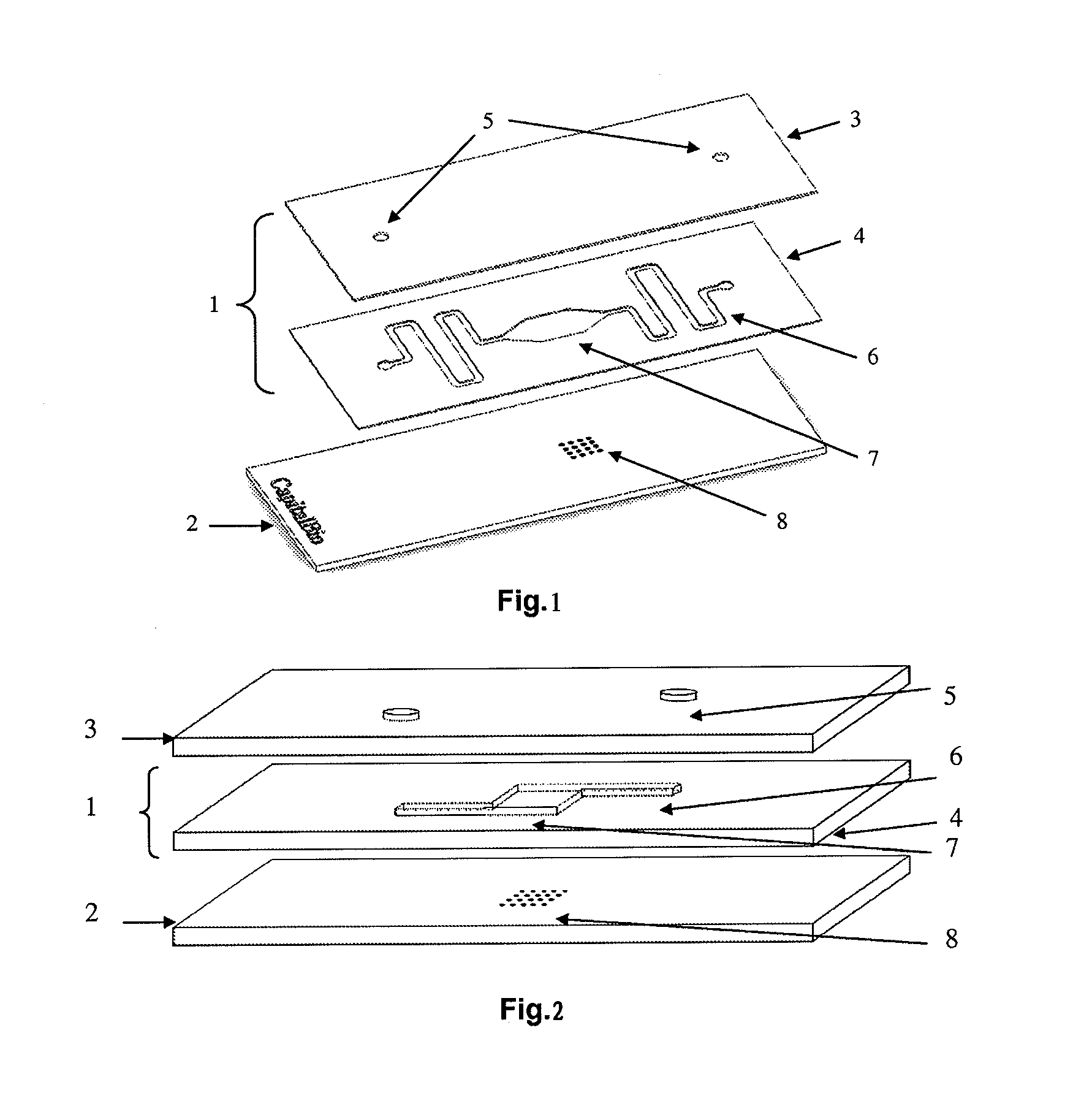
[0034]The three-dimensional structure of the automatic sample loading device containing one sample loading unit can be seen in FIG. 1, wherein 1 is the automatic sample loading device; 2 is the microarray chip, which is a glass based DNA chip or protein chip, with the size of 25×75 mm; 3 is the hydrophilic glass cover plate, after chemical modification, the lower surface of the glass cover plate, i.e., the surface contacting the microfluid layer 4, has a static contact angle of 12 degrees with water, while the upper surface has a static contact angle of 40 degrees with water; and through hole 5 is placed on the cover plate 3 for the solution to pass through; The thickness of the microfluid layer 4 is about 0.2 mm, the substrate of the microfluid layer is polyethylene terephthalate (PET), with both lower and upper surface homogenously coated by acry...

example 2

[0035]An automatic sample loading device and an automatic sample loading hybridization microarray chip containing one sample loading unit

[0036]As shown in FIG. 2, the automatic sample loading device 1 containing one sample loading unit is formed. by the hydrophilic cover layer 3 and the microfluid layer 4 through sealing, wherein after chemical modification, the lower surface of glass cover plate 3, i.e., the surface contacting the microfluid layer 4, has a static contact angle of 15 degrees with water, while the upper surface, after hydrophobic treatment, has a static contact angle of 1.00 degrees with water, and a through hole 5 is disposed on the cover layer 3 for the solution to pass through. he thickness of the microfluid layer 4 is about 0.2 mm, the substrate of the microfluid layer is polyethylene terephthalate (PET), with both lower and upper surface homogenously coated by acrylic adhesive, and a hollow microfluid channel 6 and hybridization chamber 7 are disposed on the mic...

example 3

[0037]The automatic sample loading device containing a plurality of sample loading units

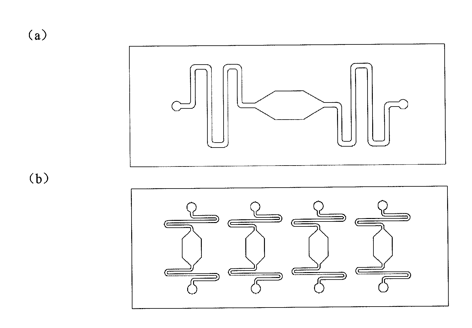
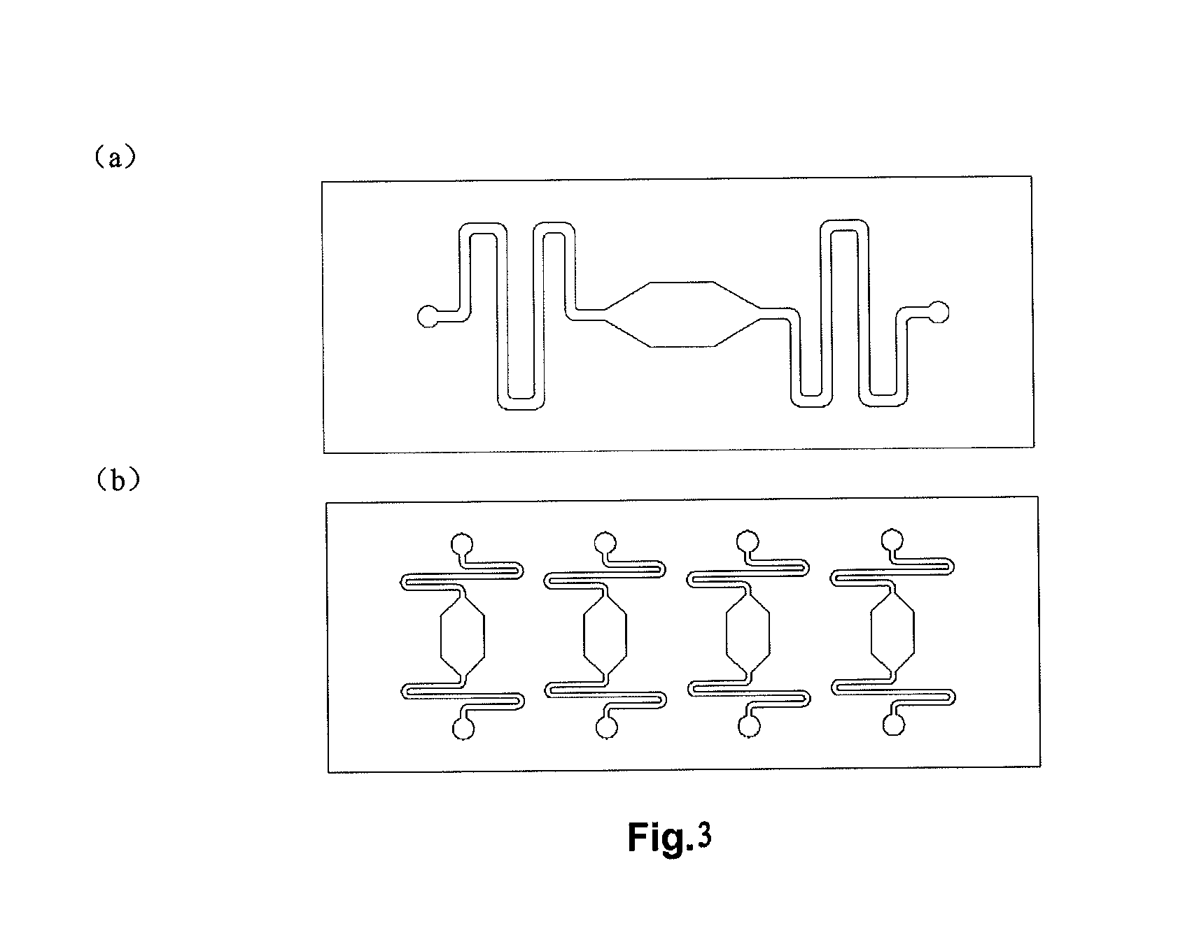
[0038]FIG. 3(b) is the schematic diagram showing an automatic sample loading device containing 4 sample loading units. The material used for the cover plate is polymethylmethacrylate (PMMA), the lower surface of the cover plate has a static contact angle of 6 degrees with water after modified by polyvinyl alcohol (PVA), while the upper surface with no modification has a static contact angle of 78 degrees with water; the material for the microfluid layer is silicon wafer.

[0039]In contrast to Example 1 and 2, the size for the cover layer and the microfluid layer is large, so that 4 sample loading units are disposed side by side; the microfluid layer of the automatic sample loading device is sealed with 4 microarray chips by adhesive, to form a plate structure with microfluid channels inside, wherein the microfluid channels in each sample loading unit are not connected with each other, while a hybri...


PUM

PropertyMeasurementUnit
contact angleaaaaaaaaaa
reciprocating frequencyaaaaaaaaaa

Abstract

An automatic injection device comprises at least an injection unit (1). The said injection unit (1) is formed by sealing a cover plate layer (3) with hydrophilic surfaces and a microfluid layer (4). The said cover plate layer (3) is provided with at least two through holes (5). he said microfluid layer (4) is provided with a hollow-out hybridization chamber (7) and at least two hollow-out microfluid channels (6). One end of each channel (6) is connected with the hybridization chamber (7), and the other end is connected with a through hole (5) of the cover plate layer (3) respectively. Taking advantage of the hydrophilicity of the cover plate, the automatic injection device makes a solution automatically enter and fill the hybridization chamber (7) and the microfluid channels (6) by the driving force of liquid surface tension. The flow uniformity of sample solution in microarray chip is achieved by the structural design of the hybridization chamber (7) and the microfluid channels (6). The automatic injection device has advantages of simple manufacture, easy operation, high hybridization efficiency, low sample cost, and automatic quantificational injection.

Description

[0001]The present application claims the priority of Chinese patent application No. 201110068676.0 filed on Mar. 22, 2011 to The Patent Office of the People's Republic of China, and titled “Automatic sample loading device for microarray chip and automatic sample loading hybridization microarray chip”, which is hereby incorporated by reference in its entirety.FIELD OF INVENTION[0002]The present invention relates to the field of biotechnology, in particular, to an automatic sample loading device for microarray chip and automatic sample loading hybridization microarray chip.BACKGROUND OF THE INVENTION[0003]Nucleic acid hybridization is based on the specific binding between complementary DNA chains, which are currently broadly used for gene expression analysis, gene phenotype analysis and clinical diagnosis etc. For conventional static nucleic acid hybridization represented by microarray chip, the hybridization process simply relies on molecular diffusion, that is, target molecules must...

Claims


Application Information

Patent Timeline
Patent Type & Authority Applications(United States)
IPC IPC(8): G01N1/10
CPCG01N1/10G01N35/1095G01N33/543C12Q1/6813G01N33/68C40B30/04C40B40/12C40B40/10C40B40/06
Inventor YE, JIAMINGWANG, PINHONGWANG, GUOQINGXING, WANLI
Owner CAPITALBIO CORP
Why Eureka
Try Eureka