Contactor and Separation Apparatus and Process of Using Same

a technology of separation apparatus and contactor, which is applied in the direction of separation process, liquid displacement, application, etc., can solve the problems of poor separation, high dispersion, and formation of emulsions, and achieve the effect of reducing the number of emulsions

Active Publication Date: 2014-01-16
MERICHEM CO
View PDF5 Cites 15 Cited by
  • Summary
  • Abstract
  • Description
  • Claims
  • Application Information

AI Technical Summary

Benefits of technology

[0007]Our invention is directed to an improved apparatus and process for separating at least two immiscible liquids into separate phases. The apparatus comprises a vessel having an interior volume that contains a shroud positioned within the interior volume. Preferably, the vessel is a vertical vessel, meaning that the vessel has generally the same diameter at the top as it does at the bottom where the denser liquid is removed. In other wo...

Problems solved by technology

Low interfacial tension (IFT) of the liquids in the admixture causes formation of emulsions and high dispersions, which manifest in the absence of a clear well defined phase boundary interface.
A poor separation could simply be tolerated, however, it would then become necessary to force the effluent through a separate mechanical separation device, such as packed bed, centrifuge, centrifugal liquid separator, hydro cyclone or the like.
These solutions have disadvantages of high capital cost and additional energy input.
This incurs additional expense and is typically not very effective because with the low interfacial tension of the system the addition of surface-active chemicals may make the problem worse.
This dispersion problem occurs in hydrocarbon treatment processes, for example, the desulfurization of kerosene using an aqueous catalyst solution via an oxidation reaction.
In such processes two liquid phases are created that can be very difficult to separate downstream because of the low interfacial tension of the two liquid phases.
If the flow of either liquid is stopped, the dispersion band may ultimately collapse over time.
However, if the production rate of this dispersion is higher than the collapse rate, the dis...

Method used


Image

  • Contactor and Separation Apparatus and Process of Using Same
  • Contactor and Separation Apparatus and Process of Using Same
  • Contactor and Separation Apparatus and Process of Using Same

Examples


Embodiment Construction

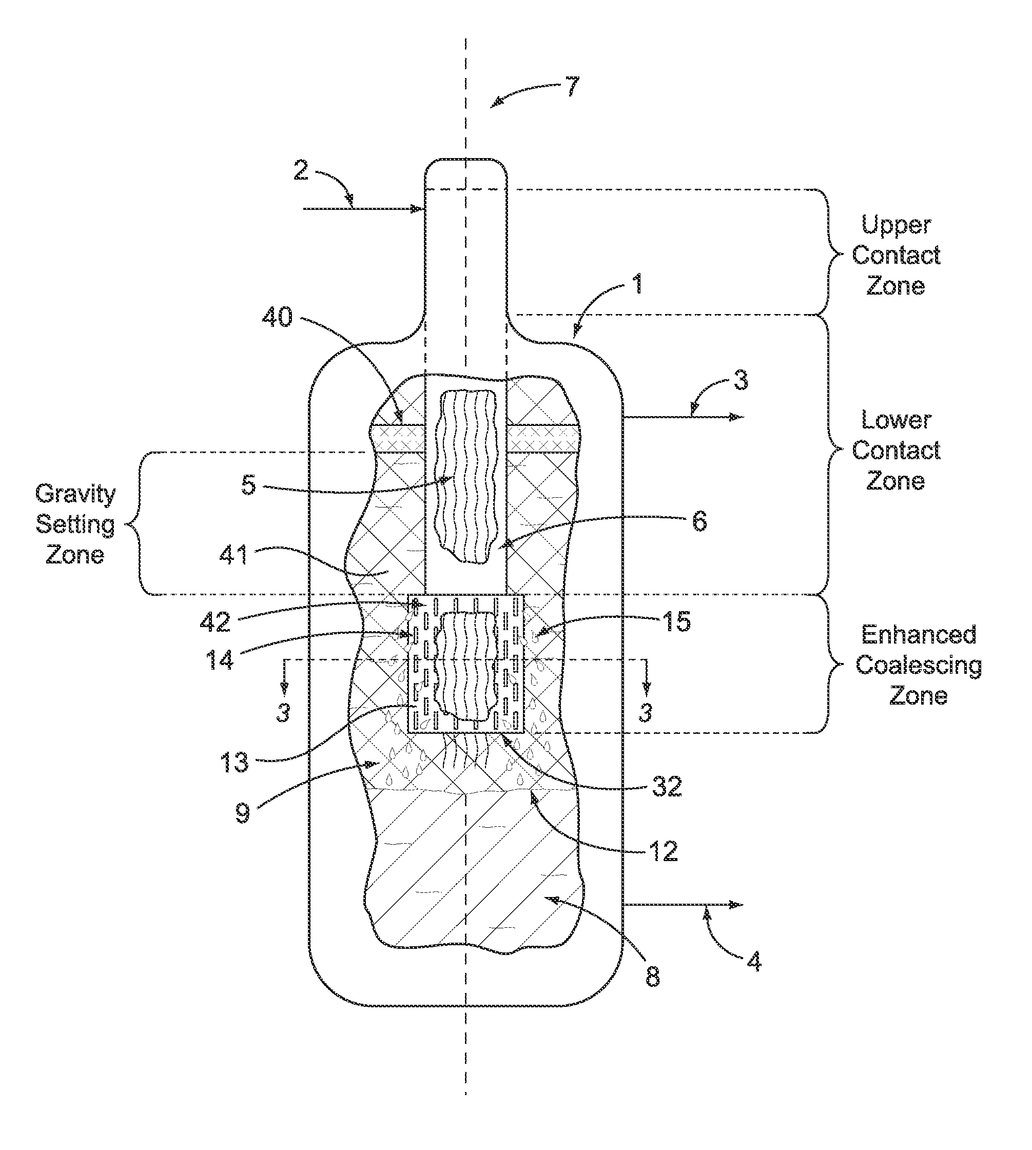
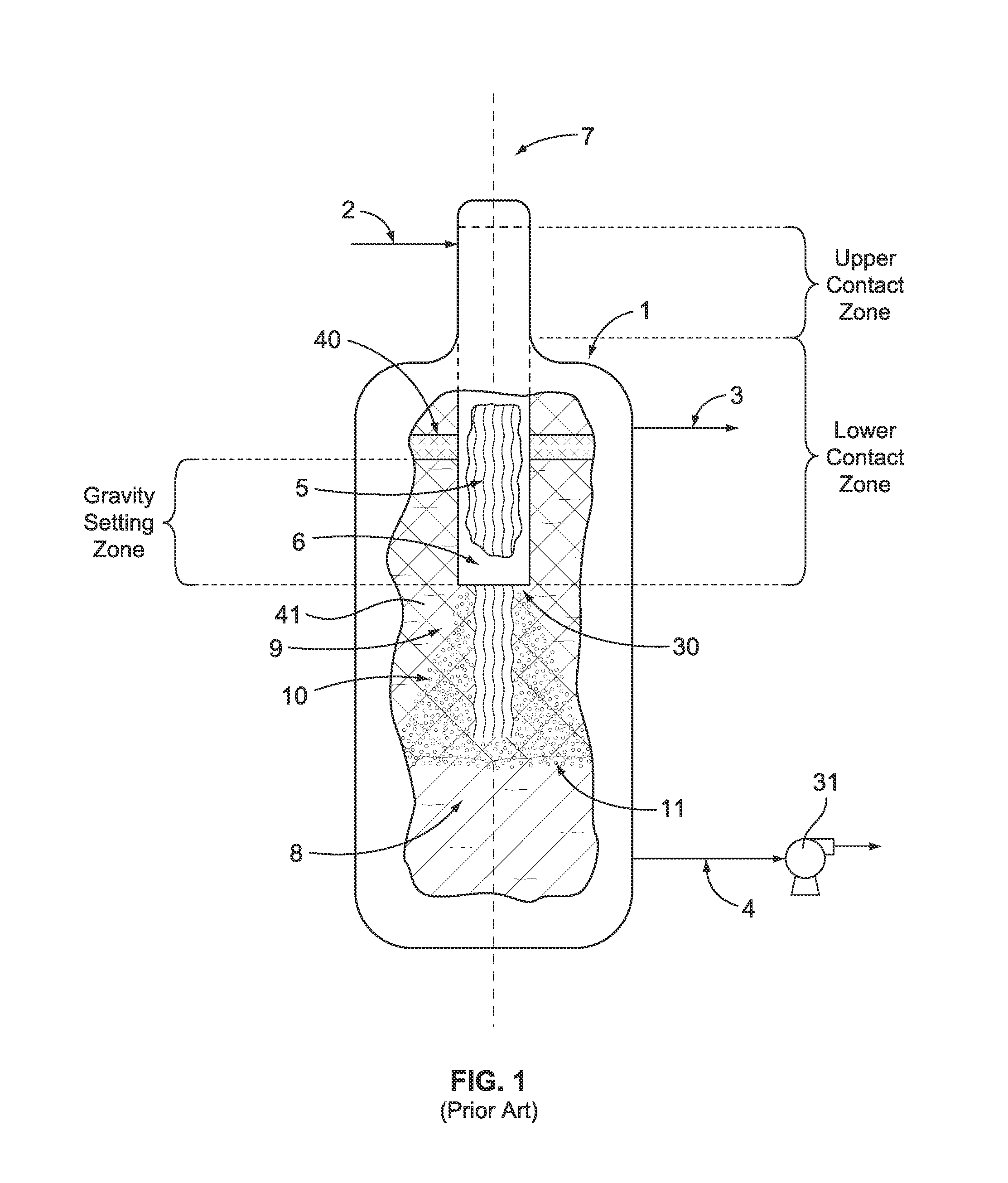
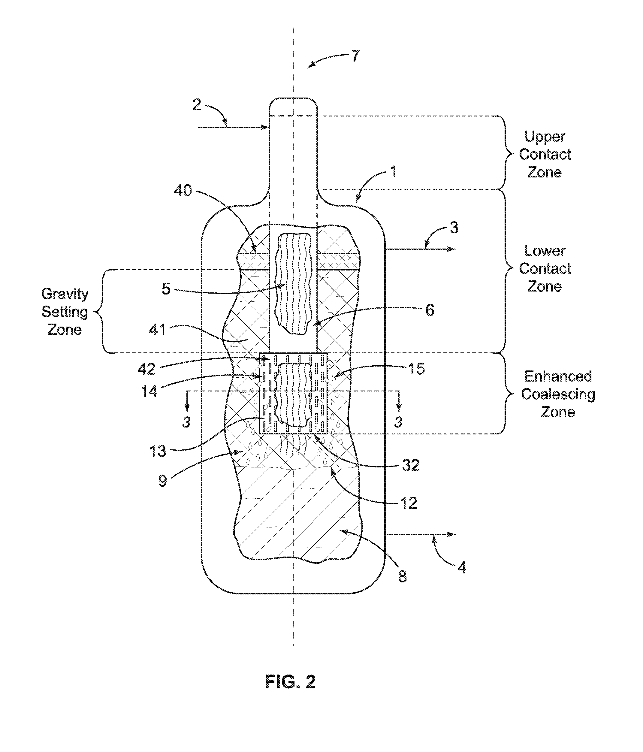
[0034]A comparison of the instant invention with an apparatus and process known in the art is helpful in understanding the improvements in our invention. To that end, FIG. 1 illustrates a prior art process and apparatus for use in a process that uses catalytic oxidation of reactants that results in the formation of an admixture comprising at least two immiscible liquids. The reactants are fed to the process and introduced to vertical vessel 1 through inlet process line 2 where the reactants contact the uppermost portion of a plurality or bundle of hanging fibers 5 that define a vertical axis 7. Notably, vertical vessel 1 does not have a large horizontal section located below the hanging fibers. Preferably the reactants pass through a liquid distributor (not shown) that is positioned at the top of the bundle of fibers. The hanging fibers 5 are contained within a shroud 6 that forces the admixture of liquids to flow parallel to the vertical axis and to contact the hanging fibers. The ...


PUM

PropertyMeasurementUnit
Fractionaaaaaaaaaa
Fractionaaaaaaaaaa
Fractionaaaaaaaaaa

Abstract

In an improved fiber-film type contactor/separator an enhanced coalescing zone is provided by the presence of a disengagement device connected to a shroud that contains a bundle of high surface area vertical hanging fibers, where the enhanced coalescing zone diverts a portion of an admixture of immiscible liquids to flow radially in a path not parallel to the vertical axis of the hanging fibers whereby the diverted portion of liquids contacts a coalescing surface to cause at least one of the liquids to coalesce into droplets. The immiscible liquids are allowed to settle into separate phase layers and first and second outlets selectively remove the higher density liquid from the lower density liquid.

Description

FIELD OF INVENTION[0001]The invention relates to a method and apparatus for contacting and separating a mixture of at least two liquids having different densities in a non-dispersive process utilizing a plurality of vertically hanging fibers contained in a shroud that terminates with a disengagement device that provides an enhanced coalescing zone (ECR). In particular, the invention is useful when the liquids have relatively low interfacial tension (IFT). The ECR eliminates or greatly reduces the accumulation of dispersed liquid mixture that can lead to carry-over and poor separation efficiency. The apparatus can be used for treating liquid hydrocarbons in order to convert acidic impurities, such as mercaptans, to less odorous sulfur compounds.BACKGROUND OF THE INVENTION[0002]In most hydrocarbon treatment processes it is often necessary at some point in the process to contact and then separate two or more liquids from each other based on density differences. One approach is to use M...

Claims


Application Information

Patent Timeline
IPC IPC(8): B01D17/032B01D29/00B23P17/04B01D17/025
CPCB01D17/045Y10T29/49716B01D17/04B01D11/043B01D17/0202B01D17/0208B01D17/047B01D2011/005
Inventor MCGEHEE, JAMES F.ZHANG, TIEJUN
Owner MERICHEM CO
Why Eureka
Try Eureka