Optical filter and sensor system

a technology of optical filters and sensors, applied in the field of optical filters and sensor systems, can solve the problems of increasing the cost and coating time involved in fabricating these conventional optical filters, difficult patterning of conventional optical filters, and low suitability of hydrogenated silicon materials

Active Publication Date: 2014-01-16
VIAVI SOLUTIONS INC
View PDF6 Cites 82 Cited by
  • Summary
  • Abstract
  • Description
  • Claims
  • Application Information

AI Technical Summary

Problems solved by technology

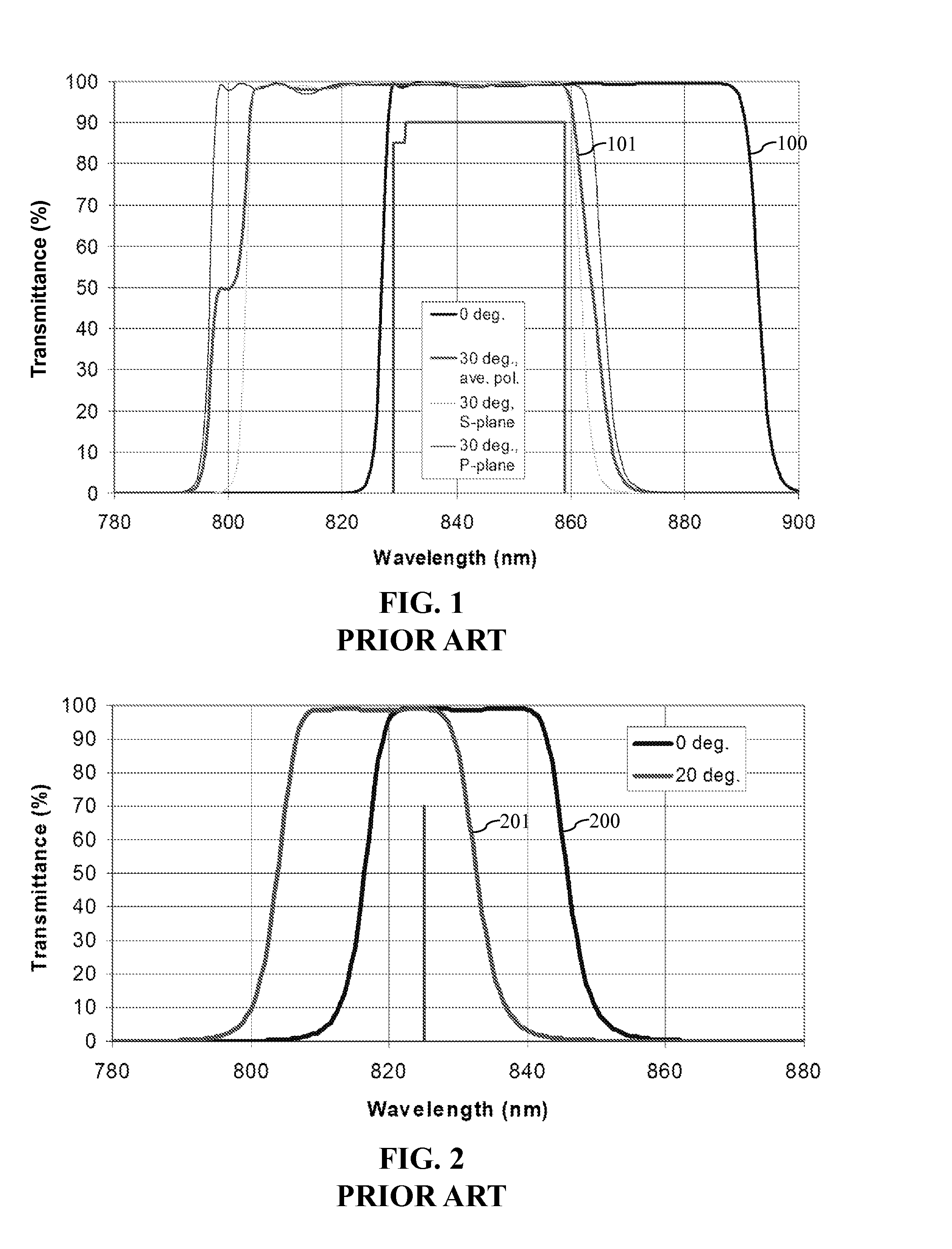
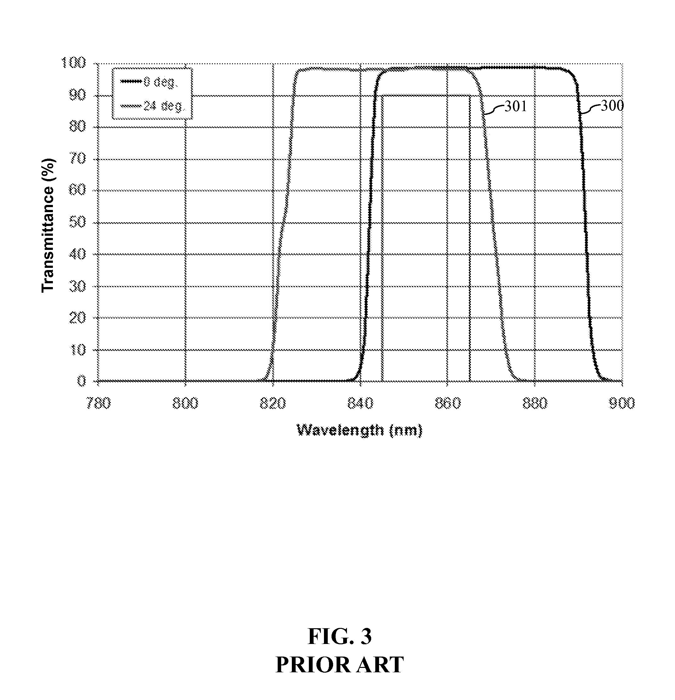
Furthermore, the large number of layers in the filter stacks and blocking stacks increases the expense and coating time involved in fabricating these conventional optical filters.
The large total coating thickness also makes these conventional optical filters difficult to pattern, e.g., by photolithography.
Unfortunately, these hydrogenated silicon materials do not have a suitably low extinction coefficient over the wavelength range of 800 nm to 1100 nm.

Method used


Image

  • Optical filter and sensor system
  • Optical filter and sensor system
  • Optical filter and sensor system

Examples


Embodiment Construction

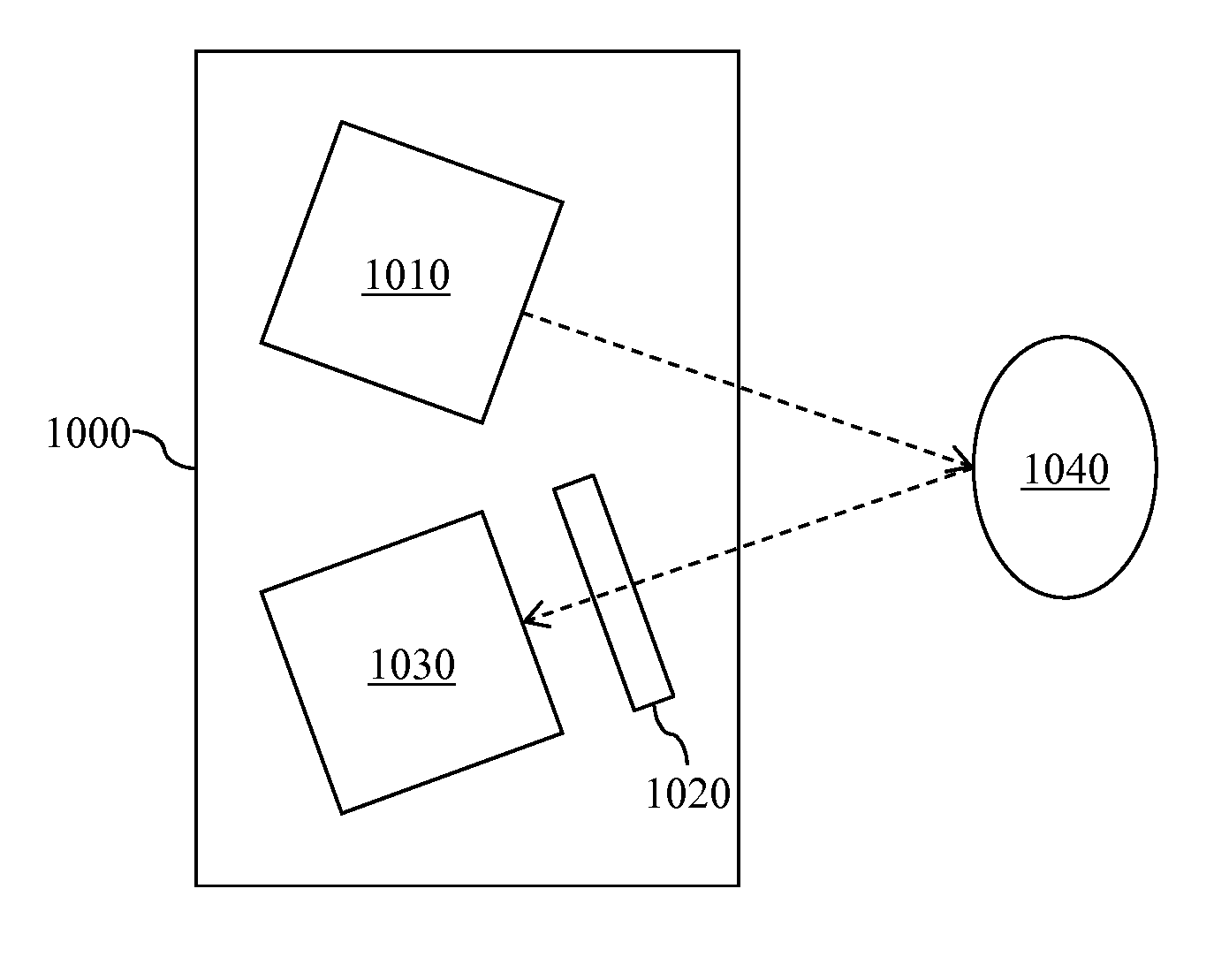
[0034]The present invention provides an optical filter including hydrogenated silicon (Si:H) layers, which is particularly suitable for use in a sensor system, such as a proximity sensor system, a three-dimensional (3D) imaging system, or a gesture-recognition system.

[0035]The optical filter of the present invention uses an improved hydrogenated silicon material, which has both a high refractive index and a low absorption coefficient over a wavelength range of 800 nm to 1100 nm, i.e., in the near-infrared wavelength range. Typically, the hydrogenated silicon material is amorphous. The hydrogenated silicon material is, preferably, produced by pulsed direct current (DC) sputtering. A sputter-deposition system suitable for producing the hydrogenated silicon material is described in U.S. Pat. No. 8,163,144 to Tilsch, et al., issued on Apr. 24, 2012, which is incorporated herein by reference.

[0036]With reference to FIG. 4, a typical sputter-deposition system 400 used to produce the hydro...


PUM

PropertyMeasurementUnit
wavelength rangeaaaaaaaaaa
refractive indexaaaaaaaaaa

Abstract

An optical filter having a passband at least partially overlapping with a wavelength range of 800 nm to 1100 nm is provided. The optical filter includes a filter stack formed of hydrogenated silicon layers and lower-refractive index layers stacked in alternation. The hydrogenated silicon layers each have a refractive index of greater than 3 over the wavelength range of 800 nm to 1100 nm and an extinction coefficient of less than 0.0005 over the wavelength range of 800 nm to 1100 nm.

Description

CROSS-REFERENCE TO RELATED APPLICATIONS[0001]This application claims priority from U.S. Provisional Patent Application No. 61 / 672,164 to Hendrix, et al., filed on Jul. 16, 2012, which is incorporated herein by reference.TECHNICAL FIELD OF THE INVENTION[0002]The present invention relates to optical filters and to sensor systems comprising optical filters. More particularly, the present invention relates to optical filters including hydrogenated silicon layers and to sensor systems comprising such optical filters.BACKGROUND OF THE INVENTION[0003]In a typical gesture-recognition system, a light source emits near-infrared light towards a user. A three-dimensional (3D) image sensor detects the emitted light that is reflected by the user to provide a 3D image of the user. A processing system then analyzes the 3D image to recognize a gesture made by the user.[0004]An optical filter, more specifically, a bandpass filter, is used to transmit the emitted light to the 3D image sensor, while su...

Claims


Application Information

Patent Timeline
Patent Type & Authority Applications(United States)
IPC IPC(8): G02B5/28G01J5/08
CPCG02B5/281G01J5/0862G02B1/115G02B5/285C23C14/08C23C14/185C23C14/548C23C14/5806H04N13/254G01J5/0802G06V40/20G02B1/11G02B5/207H04N5/33
Inventor HENDRIX, KAREN DENISEBRADLEY, JR., RICHARD A.GRIGONIS, MARIUS
Owner VIAVI SOLUTIONS INC
Why Eureka
Try Eureka