Vertically aligned arrays of carbon nanotubes formed on multilayer substrates

a technology of carbon nanotubes and arrays, applied in the direction of record information storage, chemical/physical processes, metal/metal-oxide/metal-hydroxide catalysts, etc., can solve the problems of limited density and yield of cnt arrays grown from these surfaces, and the difficulty of forming dense and well-aligned cnt arrays on metal surfaces, etc., to improve the growth rate, density and yield of nanotubes

Active Publication Date: 2014-01-16
CARBICE CORP
View PDF13 Cites 52 Cited by
  • Summary
  • Abstract
  • Description
  • Claims
  • Application Information

AI Technical Summary

Benefits of technology

[0011]Multilayer substrates for the growth and / or support of CNT arrays are provided. Multilayer substrates promote the growth of dense vertically aligned CNT arrays and provide excellent adhesion between the CNTs and metal surfaces.
[0014]The interface layer is preferably formed from a metal which is oxidized under conditions of nanotube synthesis or during exposure to air after nanotube synthesis to form a suitable metal oxide. Examples of suitable materials include aluminum. Alternatively, the interface layer may be formed from a metal oxide, such as aluminum oxide or silicon oxide. Generally, the interface layer is thin enough to allow the catalytic layer and the adhesion layer to diffuse across it. In some embodiments wherein the catalytic layer and the adhesion layer have the same composition, this reduces migration of the catalyst into the interface layer, improving the lifetime of the catalyst during nanotube growth.
[0016]In some embodiments, the CNT array is formed by vertically aligning a plurality of CNTs on the multilayer substrate described above. This can be accomplished, for example, by transferring an array of CNTs to the distal ends of CNTs grown on the multilayer substrate. In some embodiments, tall CNT arrays are transferred to the distal ends of very short CNTs on the multilayer substrate. This technique improves the bond strength by increasing the surface area for bonding.
[0019]Generally, the nanotubes are present at a sufficient density such that the nanotubes are self-supporting and adopt a substantially perpendicular orientation to the surface of the multilayer substrate. Preferably, the nanotubes are spaced at optimal distances from one another and are of uniform height to minimize thermal transfer losses, thereby maximizing their collective thermal diffusivity.
[0023]Further, subsurface diffusion of iron from the catalytic layer during nanotube growth is reduced because the same metal is on both sides of the oxide support, which balances the concentration gradients that would normally drive diffusion. Therefore, catalyst is not depleted during growth, improving the growth rate, density, and yield of nanotubes in the array.
[0025]For example, in one embodiment, the inert support for the CNT array is piece of metal foil, such as aluminum foil. In these cases, CNTs are anchored to a surface of the metal foil via an adhesion layer, metal oxide nanoparticles or aggregates, and catalytic nanoparticles or aggregates. In some instances only one surface (i.e., side) of the metal foil contains an array of aligned CNTs anchored to the surface. In other cases, both surfaces (i.e., sides) of the metal foil contain an array of aligned CNTs anchored to the surface. If desired one or more polymers may be applied to the CNT array. The CNT array may also be decorated with one or more types of metal nanoparticles. Polymers and metal nanoparticles may be applied together to the CNT array if desired. Immersing the arrays in liquid and then evaporating the liquid such that capillary forces during drying change the local and or global morphology of the CNTs may also be used to modify the CNT arrays. In other embodiments, a flowable or phase change material may be added to the CNT arrays to fill the space between the CNTs. These materials may be placed or affixed in between a heat source and a heat sink or heat spreader, such as between an integrated circuit package and a finned heat exchanger, to improve the transfer of heat from the heat source to the heat sink or heat spreader.

Problems solved by technology

However, in spite of the tremendous potential of such materials, it has proven difficult to form dense and well aligned CNT arrays on metal surfaces, and to achieve good adhesion between the metal and CNTs.
Unfortunately, CNT arrays grown from these surfaces display limited density and yield.
In addition, CNT arrays formed in this fashion are generally poorly adhered to underlying metal surfaces, because the oxide layer, incorporated to promote dense and aligned CNT growth, does not adhere well to the underlying metal surface.

Method used


Image

  • Vertically aligned arrays of carbon nanotubes formed on multilayer substrates
  • Vertically aligned arrays of carbon nanotubes formed on multilayer substrates
  • Vertically aligned arrays of carbon nanotubes formed on multilayer substrates

Examples


example 1

Preparation of Carbon Nanotube (CNT) Arrays

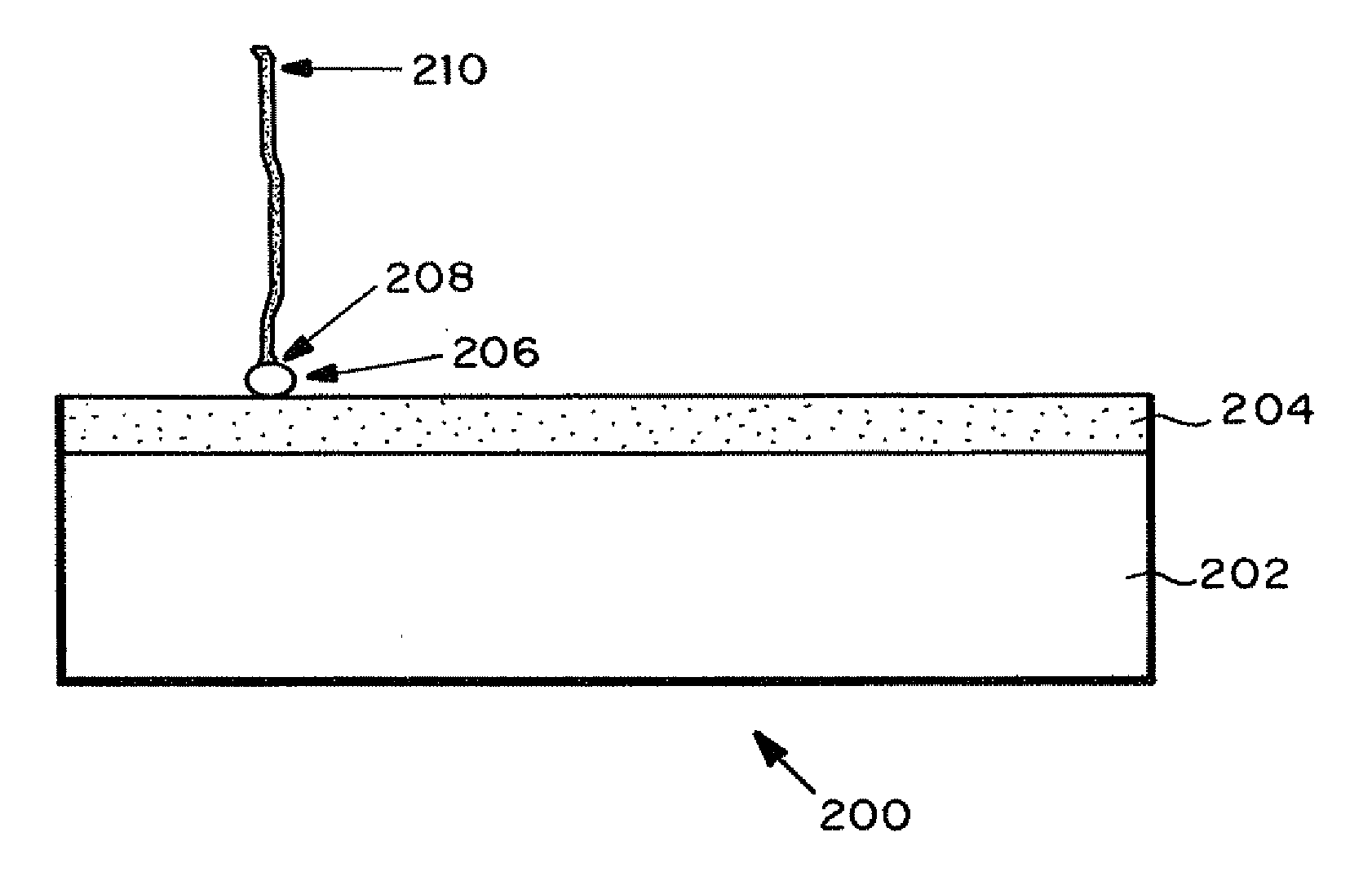
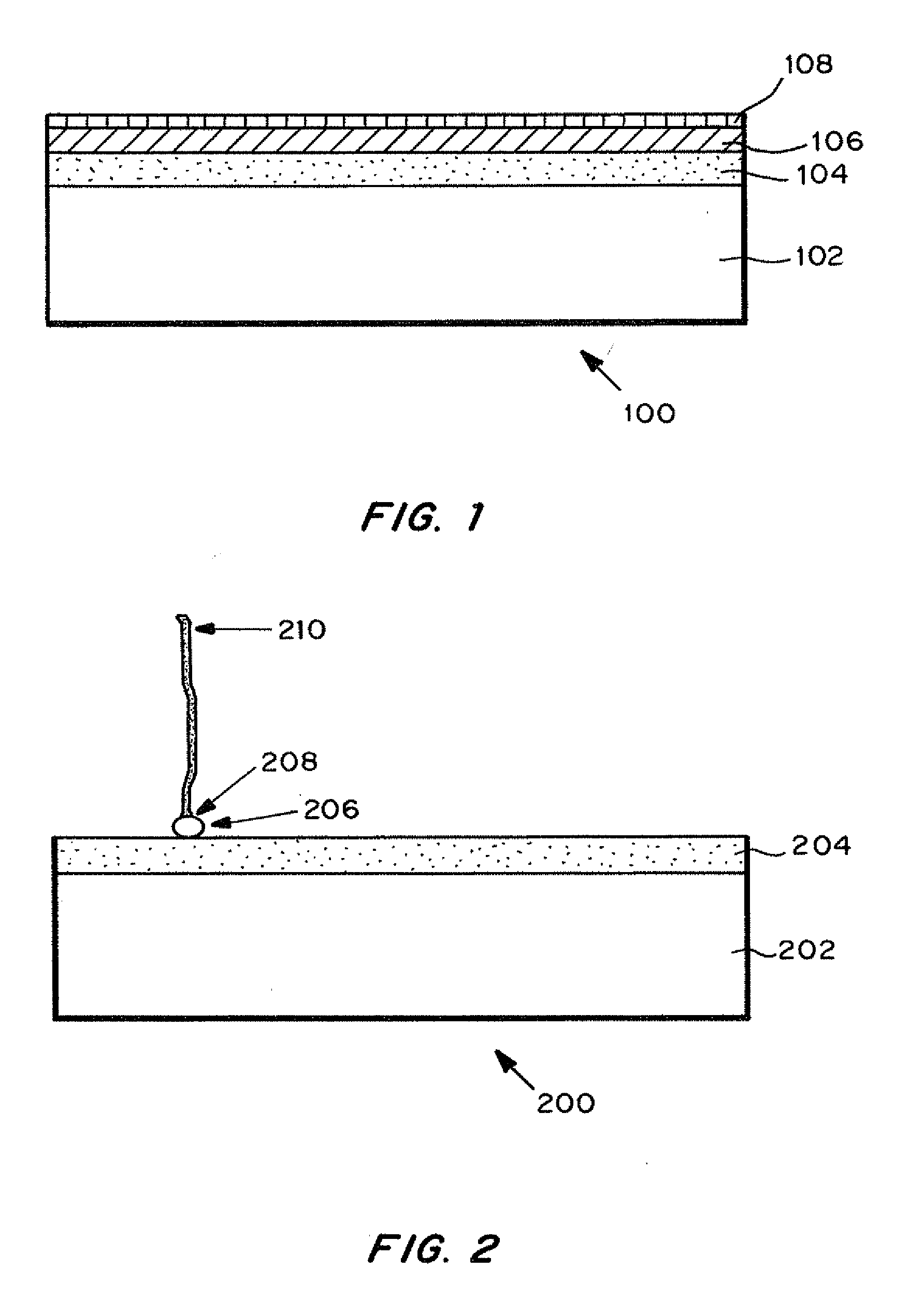
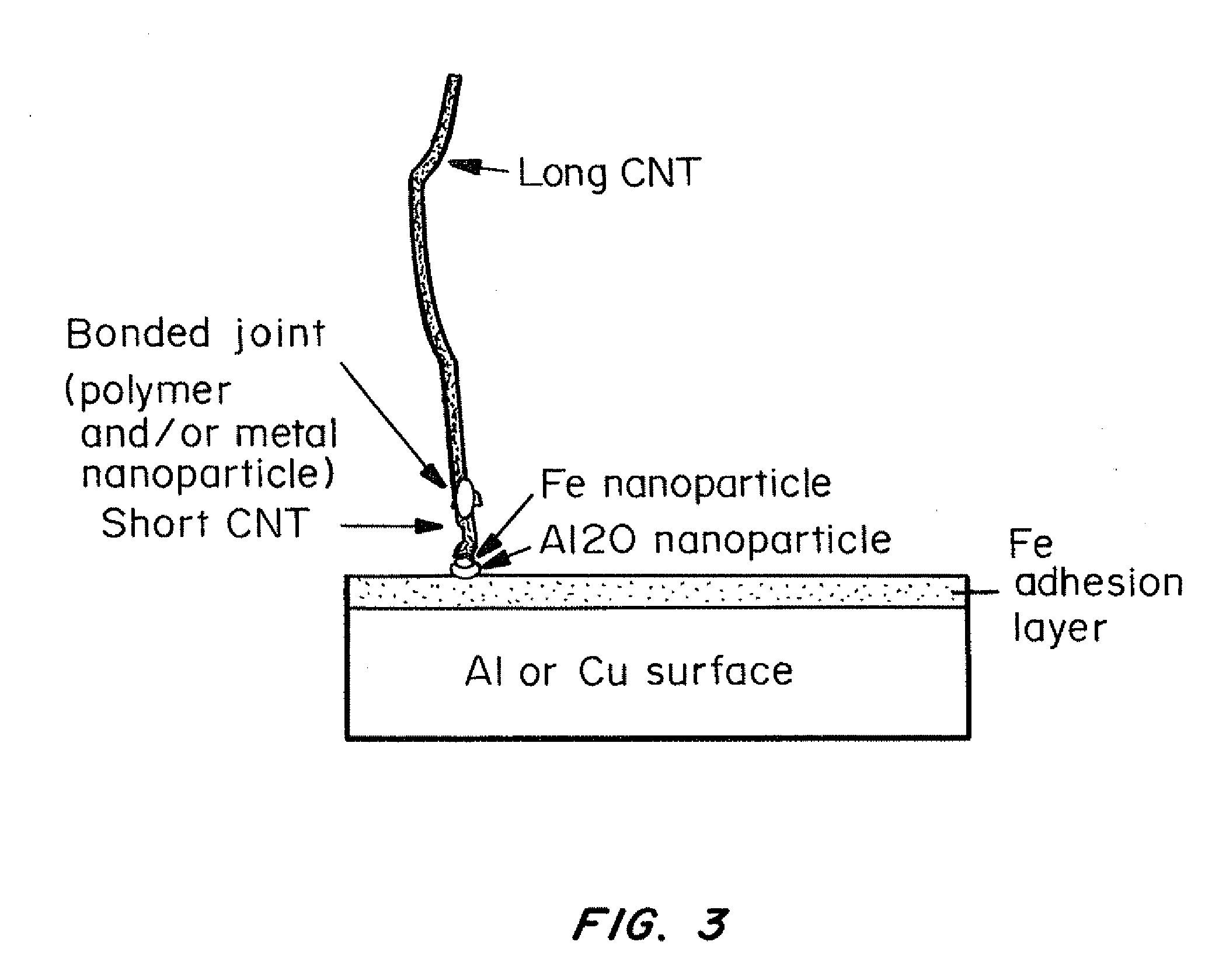
[0101]Aluminum foil was purchased at a thickness of 10 micrometers from Alfa Aesar. A piece of aluminum foil was placed in a square sample holder in a Denton Explorer electron-beam evaporator. The sample holder clamped the aluminum foil around its edges and a 5×5 inch square of the aluminum foil was exposed on the front- and backside of the sample holder, which could be flipped in-situ to deposit metal on both sides of the foil without breaking vacuum.

[0102]One side at a time, an adhesion layer of iron was deposited to a thickness of 30 nm, then an interface layer of aluminum was deposited to a thickness of 10 nm, and finally a catalytic layer of iron was deposited to a thickness of 3 nm.

[0103]The aluminum layer was allowed to cool for 10 minutes before depositing the catalytic iron film. The depositions all occurred at a chamber pressure of approximately 0.0008 mTorr. The iron adhesion layers were deposited at a rate of 0.1 nm / s; the alumi...


PUM

PropertyMeasurementUnit
thicknessaaaaaaaaaa
thicknessaaaaaaaaaa
thicknessaaaaaaaaaa

Abstract

Multilayer substrates for the growth and / or support of CNT arrays are provided. These multilayer substrates both promote the growth of dense vertically aligned CNT arrays and provide excellent adhesion between the CNTs and metal surfaces. Carbon nanotube arrays formed using multilayer substrates, which exhibit high thermal conductivity and excellent durability, are also provided. These arrays can be used as thermal interface materials.

Description

FIELD OF THE INVENTION[0001]The invention is generally related to substrates for the growth of carbon nanotube (CNT) arrays, arrays of aligned CNTs, as well as methods of making and using thereof.BACKGROUND OF THE INVENTION[0002]Carbon nanotubes (CNTs) possess a variety of useful properties, including high thermal conductivity, tensile strength, and elastic modulus. Carbon nanotubes have been investigated for applications in nanotechnology, electronics, optics, and other fields of materials science and technology.[0003]CNTs exhibit high thermal conductivity, with multi-wall carbon nanotubes (MWCTs) exhibiting thermal conductivities up to about 3,000 W / mK at room temperature, and single-wall carbon nanotubes (SWNTs) exhibiting thermal conductivities up to about 5,000 to 8,000 W / mK at room temperature.[0004]As a result, CNTs, especially vertically aligned arrays of CNTs, have attracted significant interest for use in thermal interface materials (TIMs). In order to function efficiently...

Claims


Application Information

Patent Timeline
Patent Type & Authority Applications(United States)
IPC IPC(8): B01J23/745
CPCB01J23/745Y10S977/81Y10S977/742B82Y30/00B01J23/42B01J23/44B01J23/464B01J23/466B01J23/468B01J23/75B01J23/755B82Y40/00C01B32/162C01B2202/08C09K5/14Y10T428/12431Y10T428/12493Y10T428/12576Y10T428/12611Y10T428/24975Y10T428/25Y10T428/265Y10T428/30C01B32/16C23C16/26B01J21/02B01J23/72B01J35/0006B01J35/02
Inventor COLA, BARATUNDE A.
Owner CARBICE CORP
Why Eureka
Try Eureka