
Vortex device for separating cold gas and hot gas

Active Publication Date: 2014-01-23
BEIJING ROSTAR TECH
View PDF3 Cites 10 Cited by
  • Summary
  • Abstract
  • Description
  • Claims
  • Application Information

AI Technical Summary

Benefits of technology

The patent describes two ways for a gas disk to rotate freely in a space. Firstly, it explains that if the gas disk is exposed to a centrifugal force for a long enough, it can generate enough influence on the gas pressure and temperature without needing a high rotational speed. Secondly, it explains that if the gas disk's rotation is controlled to have a small temperature difference between the outer edge and the inner edge, it can generate enough influence on the gas pressure and temperature without needing a high rotational speed. The patent also introduces a new design for the flow guiding plates that reduces turbulent flow loss and creates more uniform flow rates in the swirling gas.

Problems solved by technology

At that time, since a concept of a total temperature (stagnation temperature) of a fluid is confused with a concept of a static temperature of the fluid in Georges Ranque's expatiation upon a temperature separating phenomenon, the cold and hot gas separating phenomenon of the vortex tube was oppugned by scientists attending the meeting and generally negated in the meeting, finally resulting in interruption of further study on the vortex separation effect of temperature and the corresponding vortex tube device.
However, little progress has been made in both a basic theory and a device structure.
Although the vortex tube device is very simple in both structure and operation, an energy exchange process of the Ranque-Hilsch effect occurring in the device is extremely complicated.
Furthermore, the scientific community generally thinks that what the gas performs in the vortex tube device should be a complicated three-dimensional compressible turbulent flow.
Therefore, so far, a mathematical model by which performance of the vortex tube device can be accurately predicted has been unable to be given in application of the Ranque-Hilsch effect.
Explanations of the Ranque-Hilsch effect by the scientific community are also various, the scientific community has not yet set forth a very satisfying theoretical explanation of the Ranque-Hilsch effect, and even views of some theories themselves conflict with each other, in the basic theory.
It can be said that theoretical research on the Ranque-Hilsch effect is a major problem currently confronted by the scientific community.
The gas stream in the vortex tube device performs complicated motion.
Apparently, the above theory does not directly answer the question from microcosmic essence of a fluid temperature, but gives only a general explanation in a macroscopic aspect of the law of conservation of heat and the law of conservation of energy.
Hence, this also has led to the fact that all of the devices for achieving cold and hot gas separation by using Ranque-Hilsch effect have been limited to only the above-mentioned basic structure of the vortex tube for a long time.
In other words, it is unclear with what geometric dimensional relationship an optimal cold and hot gas separation effect can be obtained.
Since influences of each variable and a relationship between the variables on an effect of the vortex tube are substantially all unknown or indefinite, the basic structure of the vortex tube device has not been improved much for a long time.
The vortex tubes are larger in assembled equipment, have a smaller output, and suffer from big limitation of an application field.
However, the vortex tube device generates strident noise and has extremely high energy consumption when in operation since it requires that a great deal of compressed gas be used.
1. it is necessary to use a gas compressor or a similar apparatus for supplying compressed gas having a large pressure, and sharp expansion itself of the compressed gas will cause temperature drop, loud noise, and low efficiency;
2. it is necessary to dispose a big vortex generating chamber for expansion of the compressed gas, and only a part of the gas can enter the vortex traveling tube in a tangent direction to form vortex, so that the efficiency is low;
3. the diameter of the vortex tube is too small and a gas disk of a swirling is too small, and time of a cold and hot gas separation process is too short, so that the cold and hot gas separating function cannot be brought into full play;
4. the vortex blocking and returning cone will generate a great deal of useless turbulent flow in a tail of the vortex traveling tube so as to reduce the efficiency of the device; and
5. the structure of the existing vortex tube device is not suitable for manufacturing a large vortex type cold and hot gas separating device, e.g. a vortex type cold and hot gas separating device with a large aperture (having a diameter more than hundreds of millimeters, for example) which has a large air quantity and a low wind speed.

Method used


Image

  • Vortex device for separating cold gas and hot gas
  • Vortex device for separating cold gas and hot gas
  • Vortex device for separating cold gas and hot gas

Examples


first embodiment

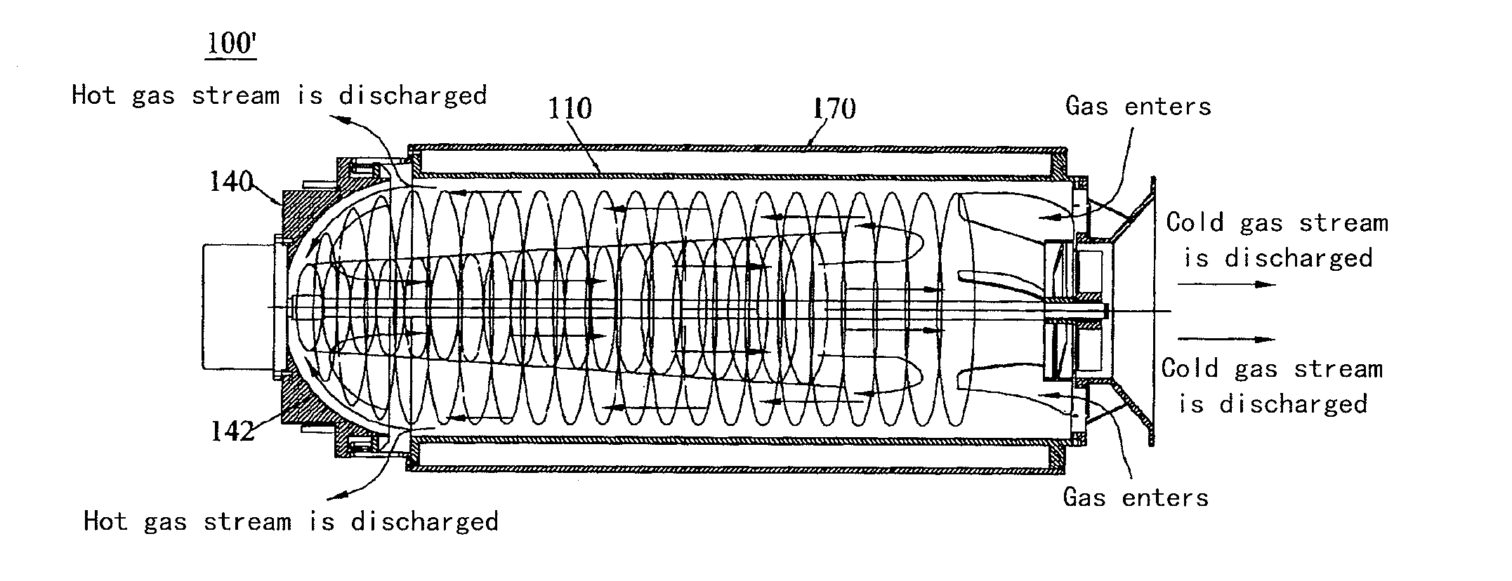
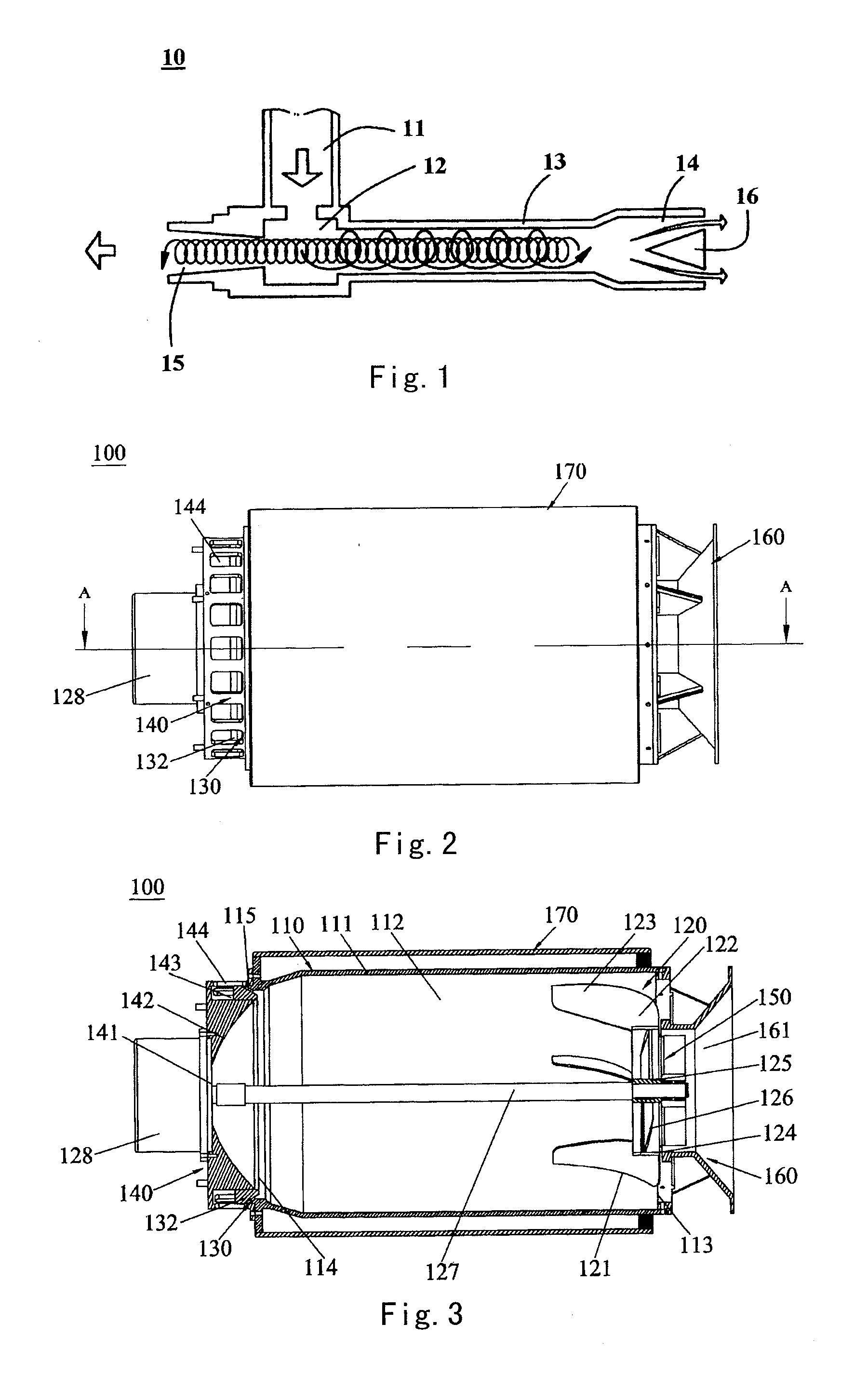
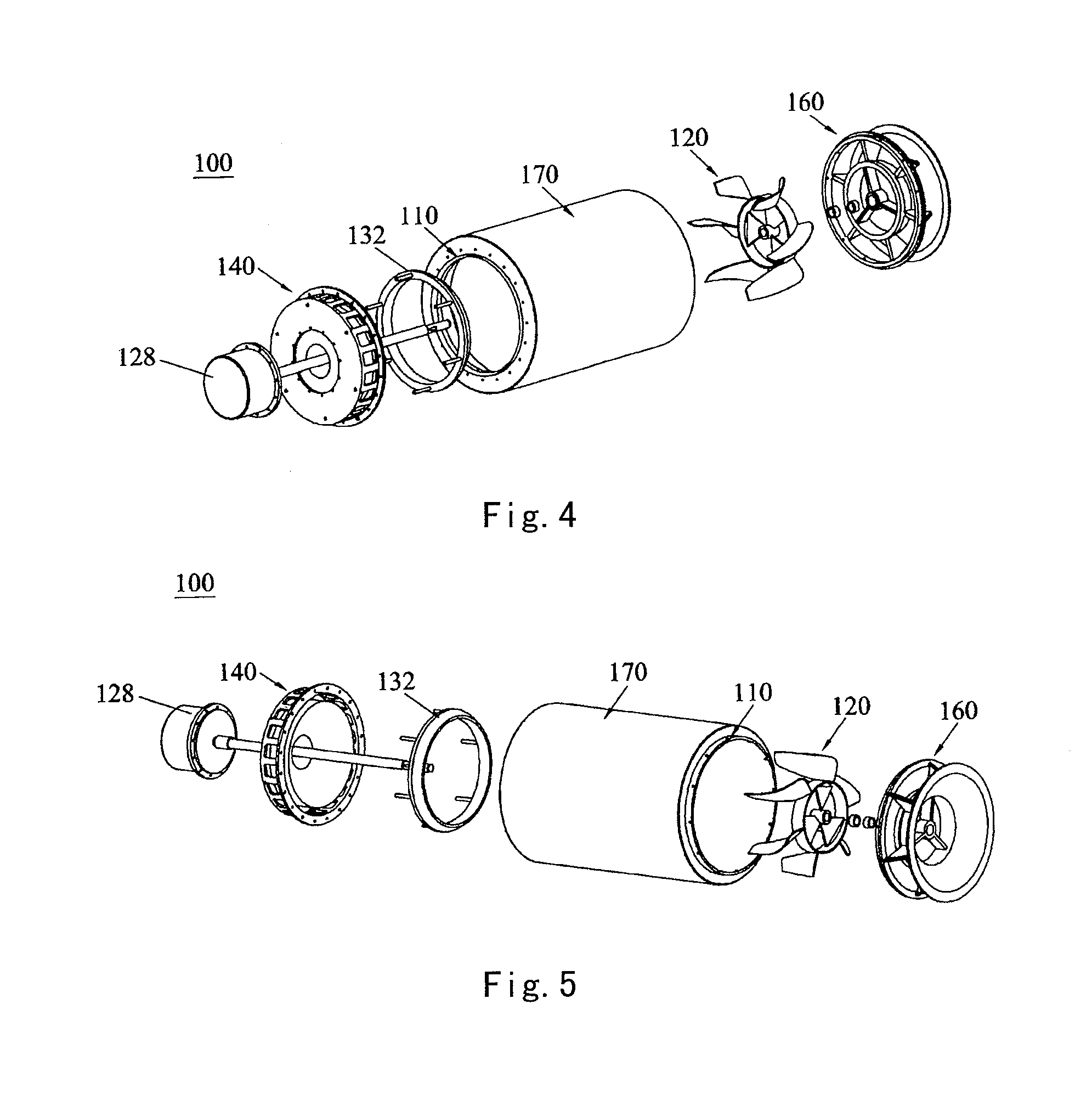
[0110]As shown in FIGS. 2-7, when considered from operation mechanism, the vortex type cold and hot gas separating device 100 according to the present invention comprises: a body 110, an intake and agitation fan device 120, a hot gas stream discharge port 130, a vortex return device 140, and a cold gas stream discharge port 150.

[0111]The body 110 has a cylindrical inner wall surface 111 defining a cylindrical inner chamber 112. The cylindrical inner chamber 112 has a first end 113 and a second end 114 opposite to the first end in an axial direction of the cylindrical inner chamber.

[0112]The intake and agitation fan device 120 is attached to the body 110 at the first end 113 of the cylindrical inner chamber 112, and is disposed to suck external gas into the cylindrical inner chamber 112 and agitate the external gas to form a first vortex rotating along the cylindrical inner wall surface 111 and traveling towards the second end 114 of the cylindrical inner chamber 112.

[0113]The hot ga...

second embodiment

[0125]FIGS. 8-11 show schematic views of a vortex type cold and hot gas separating device 200 according to the present invention.

[0126]As shown in FIGS. 8-11, the vortex type cold and hot gas separating device 200 according to the second embodiment of the present invention also comprises a body 110, an intake and agitation fan device 120, a hot gas stream discharge port 130, a vortex return device 140, and a cold gas stream discharge port 150.

[0127]A main difference between the second embodiment and the first embodiment shown in FIGS. 2-7 is that the intake and agitation fan device 120 comprises an intake fan 210 and an agitation fan 220 which are separate from each other in the vortex type cold and hot gas separating device 200 according to the second embodiment of the present invention. The intake fan 210 comprises a plurality of intake blades 211 which are disposed to be adapted to suck external gas into the cylindrical inner chamber 112. The agitation fan 220 comprises a plurali...

third embodiment

[0137]FIGS. 12-14 show schematic views of a vortex type cold and hot gas separating device 300 according to the present invention.

[0138]As shown in FIGS. 12-14, the vortex type cold and hot gas separating device 300 according to the third embodiment of the present invention comprises: a body 110, a fan 310 (not shown in FIG. 12, referring to FIG. 13 or 15) disposed outside the body, an gas inlet 320 disposed in the body 110, a hot gas stream discharge port 130, a vortex return device 140, and a cold gas stream discharge central tubular mount 330 with a cold gas stream discharge passage. The fan 310 used in the present invention is preferably a high-speed fan, and a velocity of gas stream stably outputted by the high-speed fan can reach Mach 1 / 8 or more, for example specifically may be Mach 1 / 7, Mach 1 / 6, Mach 1 / 5, Mach 1 / 4, Mach 1 / 3, Mach 1 / 2, 1 / 2, Mach 2 / 3, Mach 3 / 4, Mach 4 / 5, Mach 5 / 6, Mach 6 / 7, Mach 7 / 8, even may approach Mach 9 / 10 (the so-called sonic barrier critical value), an...


PUM

PropertyMeasurementUnit
Temperatureaaaaaaaaaa
Pressureaaaaaaaaaa
Flow rateaaaaaaaaaa

Abstract

A vortex type cold and hot gas separating device (100) includes a body (110) having a cylindrical inner wall surface (111), the inner wall surface (111) defining a cylindrical inner chamber (112) having a first end (113) and a second end (114); an intake and agitation fan device (120) attached to the body (110) at the first end (113) which sucks external gas into the cylindrical inner chamber (112) and agitates the external gas to form a first vortex traveling towards the second end (114); a hot gas stream discharge port (130) located at or adjacent to an edge of the second end (114) to discharge a part of gas of the first vortex traveling to the hot gas stream discharge port (130) out of the cylindrical inner chamber (112); a vortex return device (140) located at the second end (114) to return the remaining gas of the first vortex which is not discharged from the hot gas stream discharge port (130), thereby forming a second vortex traveling towards the first end (113) of the cylindrical inner chamber (112) through a cyclone core of the first vortex; and a cold gas stream discharge port (150) located at a radial center of the first end (112) of the cylindrical inner chamber or located adjacent to and around the radial center. A temperature of the gas discharged from the hot gas stream discharge port (130) is higher than a temperature of the gas discharged from the cold gas stream discharge port (150).

Description

BACKGROUND OF THE INVENTION[0001]1. Field of the Invention[0002]The present invention generally relates to an energy separating device, and particularly to a vortex type cold and hot gas separating device for separating a gas into cold and hot gas streams by using Ranque-Hilsch effect.[0003]2. Description of the Related Art[0004]Historically, the phenomenon of the Ranque-Hilsch effect is first found by Georges Ranque, a French metallurgical engineer, in 1930. At that time, Georges Ranque found in an experiment a vortex cooling effect in a cyclone separating device, i.e., a temperature at a center of a gas stream is different from temperatures of peripheral layers of the gas stream, the center of the gas stream has a lower temperature, while the outer edge of the gas stream has a higher temperature, in the cyclone separating device. According to this phenomenon, Georges Ranque subsequently designed a first vortex tube device which can separate energy in the history of mankind and fil...

Claims


Application Information

Patent Timeline
IPC IPC(8): B01D45/16
CPCB01D45/16F25B9/04B01D45/08B01D45/12
Inventor YAO, QIHUAIYAO, ZHEN
Owner BEIJING ROSTAR TECH
Learn More