Whitening filter configuration method, program, and system

Inactive Publication Date: 2014-02-06
IBM CORP
View PDF5 Cites 13 Cited by
  • Summary
  • Abstract
  • Description
  • Claims
  • Application Information

AI Technical Summary

Benefits of technology

The present invention provides a technique for automatically configuring a whitening filter that optimizes the resolution of frequency bands where poles are concentrated. Additionally, it provides a technique for constituting a reverse (whitening) filter that enhances the resolution of bands with spectral peaks while reducing the effect of disturbances on low SN ratio multi-tone signals, resulting in fewer errors during the identification process.

Problems solved by technology

This means disturbance factors related to observation results include a closed-loop control system that is an adaptive system with very short times, and plant impacts that cannot be assumed based on experience with conventional artificial satellites.
Usually, external disturbances affecting artificial satellites pose difficult problems for low-frequency band signals.
However, actually, the low SN ratio signals mentioned above have many unknown frequency signals (multi-tone signals) embedded in the noise.

Method used


Image

  • Whitening filter configuration method, program, and system
  • Whitening filter configuration method, program, and system
  • Whitening filter configuration method, program, and system

Examples


Embodiment Construction

[0025]The following is an explanation of examples of the present invention with reference to the drawings. In the drawings, the same objects are denoted by the same reference symbols unless otherwise indicated. The following explanation is an embodiment of the present invention, and it should be understood that the present invention is in no way limited to the embodiment shown here.

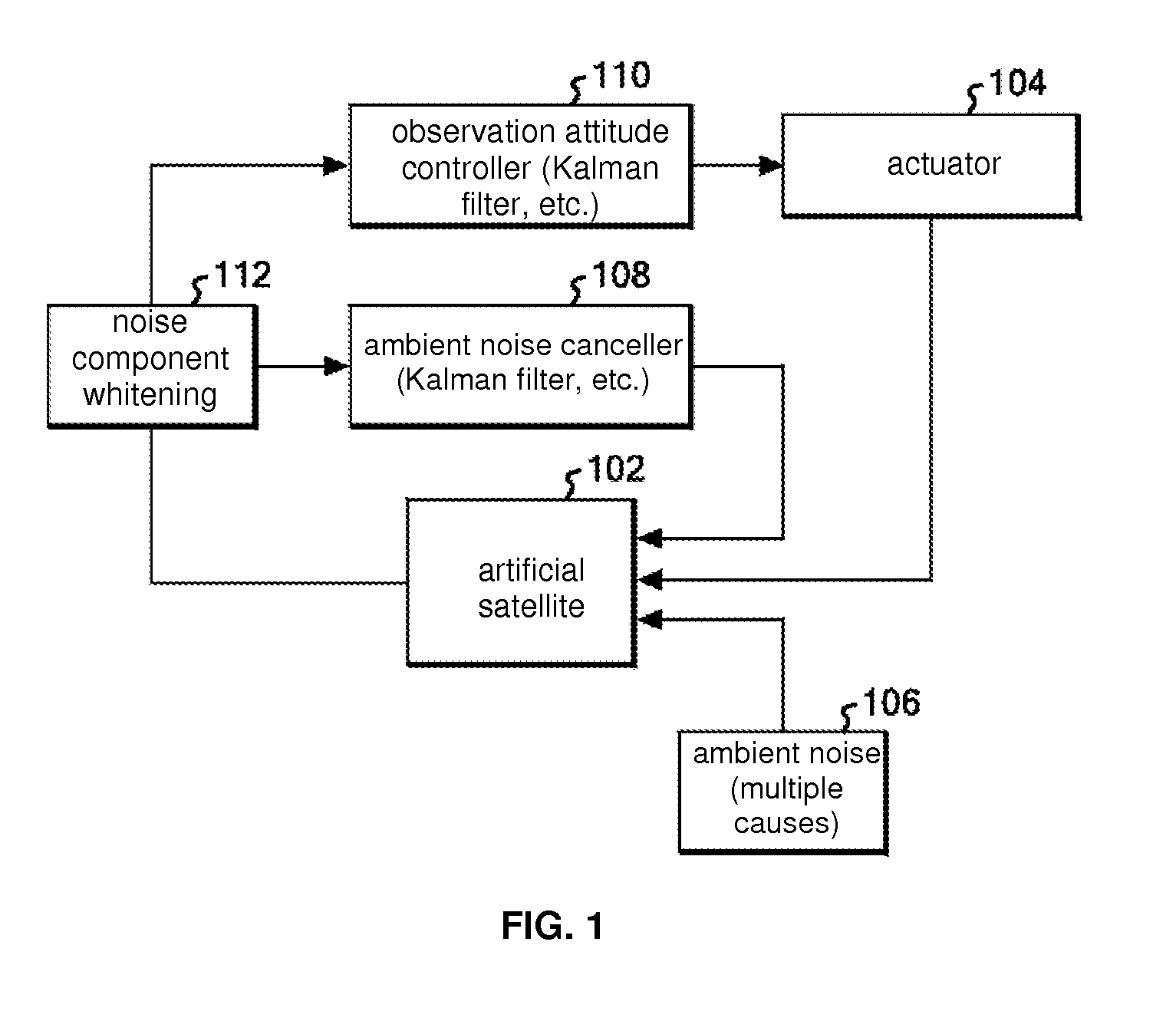
[0026]FIG. 1 is a block diagram of a control system for an artificial satellite. In FIG. 1, the artificial satellite 102 is driven and controlled by an actuator 104. The actuator 104 is involved in the system related to attitude control, the system related to propulsion, and other systems.

[0027]The artificial satellite 102 travels in orbit while being subjected to a variety of disturbances such as distortions of the gravity field, the gravitational pull of the sun and moon, solar winds, air molecules in the atmosphere, and ions. These disturbances are indicated as ambient noise 106 in FIG. 1.

[0028]Because...


PUM


Abstract

A system is configured so that signals passed through an all-pass filter using warp parameter λ are whitening-filtered, and so that the frequency axis is restored by an all-pass filter using warp parameter λ. This optimizes the whitening filter by determining the optimum λ. First, the AR order p is automatically estimated using λ=0. A spectral distance dλ is computed using a discrete Fourier transform spectrum value passed through an all-pass filter using warp parameter λ and a discrete AR spectrum value passed through an all-pass filter using warp parameter λ. The λ which minimizes the spectral distance dλ is set as the warp parameter, and a whitening filter is configured in which the warp parameter has been optimized.

Description

[0001]The present application claims the benefit of priority of Japanese Patent Application Serial Number 2012-169207, filed Jul. 31, 2012 with the Japanese Patent Office (JPO), the contents of which are herein incorporated by reference in its entirety.TECHNICAL FIELD[0002]The present invention relates to a configuration technique for a whitening filter that removes colored noise.BACKGROUND[0003]Precision pole estimation methods are currently used in a wide variety of fields, such as DNA structural analysis in nuclear magnetic resonance spectroscopy (NMR) (see, for example, Murata, Kubota, “Precision Pole Estimation Method Based on AR Process and an Application to the NMR Structural Analysis”, IEICE A, Vol. J91-A, No. 8, pp. 772-781, August 2008).[0004]Plans are in the works to launch and operate extremely small satellites called “nano-satellites” at much lower cost than conventional satellites, and disturbance component analysis of attitude control signals for nano-satellites is on...

Claims


Application Information

Patent Timeline
IPC IPC(8): H03H17/02
CPCH03H17/0294H03H17/0255
Inventor SHIMIZU, JUNYA
Owner IBM CORP
Why Eureka
Try Eureka