Electric excitation permanent magnet switch, electric excitation permanent magnet switch reluctance motor and electric excitation method

a technology of electric excitation permanent magnet switch and reluctance motor, which is applied in the direction of motor/generator/converter stopper, dynamo-electric converter control, etc., can solve the problem of limiting the performance to volume ratio of this type of motor, affecting the full performance of the excellent properties of switched reluctance motor, and relatively high driving energy consumption

Active Publication Date: 2014-02-27
DAI SHANSHAN
View PDF12 Cites 13 Cited by
  • Summary
  • Abstract
  • Description
  • Claims
  • Application Information

AI Technical Summary

Problems solved by technology

However, because neither the stator nor the rotor has permanent magnet used for excitation, higher electric excitation power is required to obtain high output torque, therefore the performance to volume ratio of this type of motors is restricted, and there is fairly high driving energy consumption.
However, the structures of this type of motors have not broken the practice of traditional switched reluctance motors wherein the stator housing and rotor iron core are used to form a magnetic path to produce torque, this structure of integral magnetic conduction not only involves long magnetic path and high loss, magnetic interference and flux leakage cannot be avoided between the magnetic salient poles, these factors have affected and hindered the full performance of the excellent properties of switched reluctance motors, and restricted their extensive use.
Also, existing switched reluctance motors have the disadvantages of high torque fluctuation and noise, which are unfavorable to the service life of drive parts, in short, the indicators of existing switched reluctance motors, such as output torque, energy consumption and power to volume ratio, are not quite ideal.

Method used


Image

  • Electric excitation permanent magnet switch, electric excitation permanent magnet switch reluctance motor and electric excitation method
  • Electric excitation permanent magnet switch, electric excitation permanent magnet switch reluctance motor and electric excitation method
  • Electric excitation permanent magnet switch, electric excitation permanent magnet switch reluctance motor and electric excitation method

Examples


embodiment 1

[0067]The structure of this embodiment is as shown in attached FIG. 9, the sectional view of the structure of this embodiment is as shown in attached FIG. 10.

[0068]In this embodiment the stator has 8 electric excitation permanent magnet switch components, these 8 electric excitation permanent magnet switch components are fixed symmetrically at equal spacing on the motor housing inner wall, in the electric excitation permanent magnet switch component the protruding direction of soft magnet salient pole 102 and soft magnet salient pole 103 is vertical to the plane of iron core 104 and permanent magnet 106, pointing to the motor rotating shaft 109. The rotor shaft seat 108 and rotating shaft 109 are fixed, the 6 strip-shaped iron cores, with the rotating shaft 109 as the symmetric axis, are fixed symmetrically at equal spacing on the rotor shaft seat 108, each strip-shaped iron core has two salient poles, the extruding parts of the strip-shaped iron core salient pole 105 and strip-shap...

embodiment 2

[0071]The structure of this embodiment is as shown in attached FIG. 12.

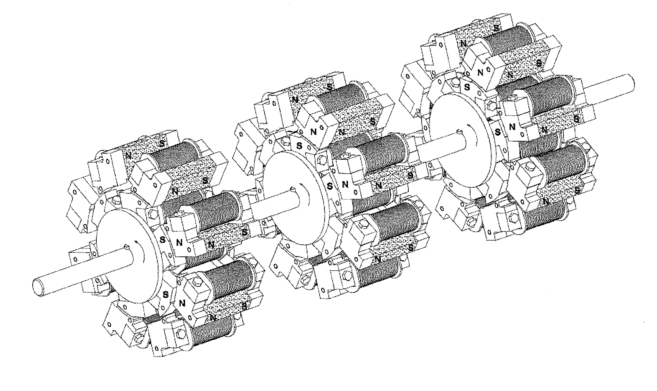
[0072]This embodiment is a further structure on the basis of the motor given in the afore-said Embodiment 1. The motor given in the afore-said Embodiment 1 is an individual motor in this embodiment. Three individual motors share one rotating shaft. As shown in attached FIG. 12, the relative positions between the stators of the three individual motors are completely identical, i.e. there is no rotating angle difference between the radial centerlines of the salient poles of the stator switch components of the three individual motors, while between the radial centerlines of the salient poles of the rotor strip-shaped iron core of the three individual motors, there is a rotating angle difference α, Attached FIG. 13 shows the sectional view of the individual motor in the front, Attached FIG. 14 shows the sectional view of the individual motor in the middle, and Attached FIG. 15 shows the sectional view of the individu...

embodiment 3

[0075]The structure of this embodiment is as shown in Attached FIG. 16 and Attached FIG. 17.

[0076]In this embodiment the stator is formed by 8 electric excitation permanent magnet switch components, these 8 electric excitation permanent magnet switch components are fixed symmetrically at equal spacing on the motor housing inner wall, and the 8 electric excitation permanent magnet switch components on the stator are mutually in a magnetically isolated state, in the stator electric excitation permanent magnet switch component, the protruding direction of soft magnet salient pole 305 is vertical to the plane of iron core exciting coil 301 and permanent magnet 303, pointing to the motor rotating shaft 304. Each stator electric excitation permanent magnet switch component has two magnetic salient poles, these two magnetic salient poles are axially distributed along the rotating shaft, the 8 switch components have a total of 8×2 magnetic salient poles. In this embodiment the rotor is form...


PUM


Abstract

Two magnetic poles of a permanent magnet of a permanent magnet switch and the two ends of an iron core wound with an excitation coil are connected to each other with the soft magnet having a salient pole. A motor uses the switch as the basic component of the stator and rotor, with two magnetic salient poles of each component being arranged axially, wherein the salient pole of the stator component and that of the rotor component are arranged in an opposite manner with an air gap, the excitation coil of the stator component and the rotor component at the symmetric axis position is taken as a phase line to access an excitation control power supply after serial connection or parallel connection. Electric excitation is carried out on the combined motor formed by shaft connection and rotation dislocation among single motors and the stator component in a bi-phase way simultaneously.

Description

FIELD OF THE INVENTION[0001]This invention is related to the technical field of switched reluctance motors, especially an electric excitation permanent magnet switch and the switched reluctance motor formed by using this electric excitation permanent magnet switch and its electric excitation method.BACKGROUND OF THE INVENTION[0002]Existing switched reluctance motors are in the doubly salient structure, the rotor is formed by laminating silicon steel sheets, with neither winding nor permanent magnet, poles of the stator are wound with exciting windings, the exciting current is input into the stator exciting windings, so that stator salient poles and rotor salient poles interact to produce a torque. The switched reluctance motor operates on the “minimum reluctance principle”, after energizing, the magnetic path has the trend of changing to the minimum reluctance. When the rotor salient poles and stator salient poles are dislocated, the air gap is big, and so is the reluctance; once th...

Claims


Application Information

Patent Timeline
Patent Type & Authority Applications(United States)
IPC IPC(8): H01H36/00
CPCH01H36/00H02K21/44H02K41/033H02K2201/15
Inventor DAI, SHANSHANLU, XIAOFENG
Owner DAI SHANSHAN
Why Eureka
Try Eureka