Apparatus and method for molding plastic materials

a technology of plastic materials and molding apparatus, which is applied in the direction of dough shaping, application, manufacturing tools, etc., can solve the problems of too expensive or impractical to produce large, voluminous or very heavy parts using this method, and the slowness of the pellet method, so as to achieve a fine level of control

Active Publication Date: 2014-03-06
SIGNATURE SYST GRP LLC
View PDF20 Cites 11 Cited by
  • Summary
  • Abstract
  • Description
  • Claims
  • Application Information

AI Technical Summary

Benefits of technology

[0011]A material delivery, mold filling and compression molding system is provided that allows for the efficient melting, flow, and delivery of molten plastic material into an open mold section, and for the compression of the material into the desired part. The apparatus and system is controlled by a central controller which integrates the various components of the system and allows for a fine level of control over the process and the system.

Problems solved by technology

Because of the high pressures required, it is often too expensive or impractical to produce large, voluminous or very heavy parts using this method.
The pellet method is relatively slow, in that material must be heated in the mold at the same time compression occurs and subsequently, the mold must be cooled from its heated state to allow forming of the part under pressure.
The fillet method is slow as well, since the fillet must be generated by an extruder in advance of placement in the tool and delivery of the fillet into the mold is generally manual or minimally mechanized.
Additionally, use of a single or even multiple fillets, which must be compressed across the face of the mold, can result in built in material stresses because of the distance within the mold that molten material must be shifted during its curing and compression.
This may lead to lack of structural integrity or subsequent warping, shrinkage or other deformation as the component seeks to return to the base configuration which may be exacerbated under certain environmental conditions.
Additionally, the area where two fillets may meet and combine or a single fillet overlaps during the compression and cooling process can be a structural weak point, as the discrete material may not combine or integrate fully, even under high pressure.
The particular arrangement of the gates in a lateral orientation experiences reduced effectiveness as the viscosity of the web of molten material is decreased, based upon the nature of the flow gates.
Furthermore, material begins to cure immediately upon being deposited into the open tool and as a result of its exposure to ambient air, the plastic material deposited earlier in the deposit cycle will be at a different temperature, viscosity and / or state of cooling during its compression, thus reducing the controllability of the process and the quality of the final part.
This results in longer cycle times than necessary to compress the component, as well as a longer time for plastic to cool, begin setting and lose viscosity before being compressed.

Method used


Image

  • Apparatus and method for molding plastic materials
  • Apparatus and method for molding plastic materials
  • Apparatus and method for molding plastic materials

Examples


Embodiment Construction

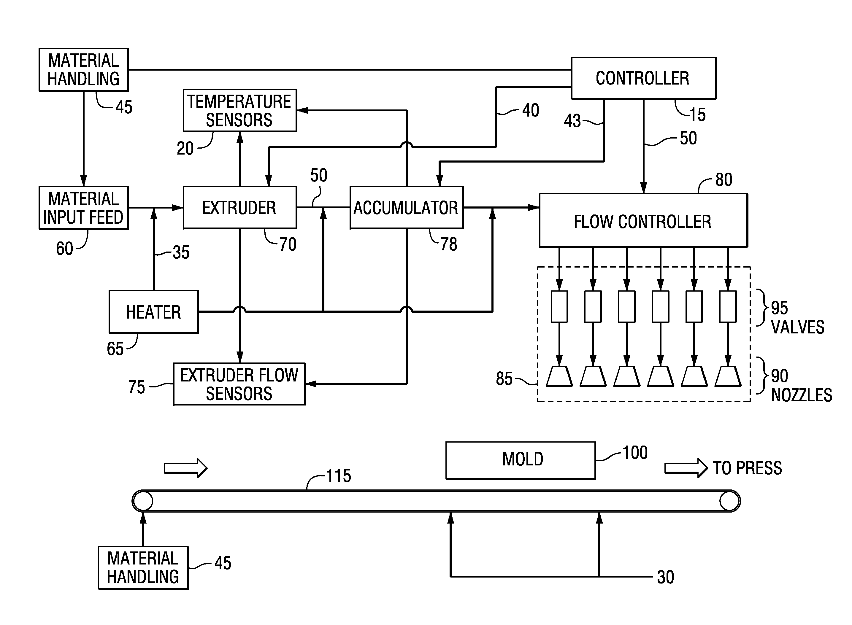
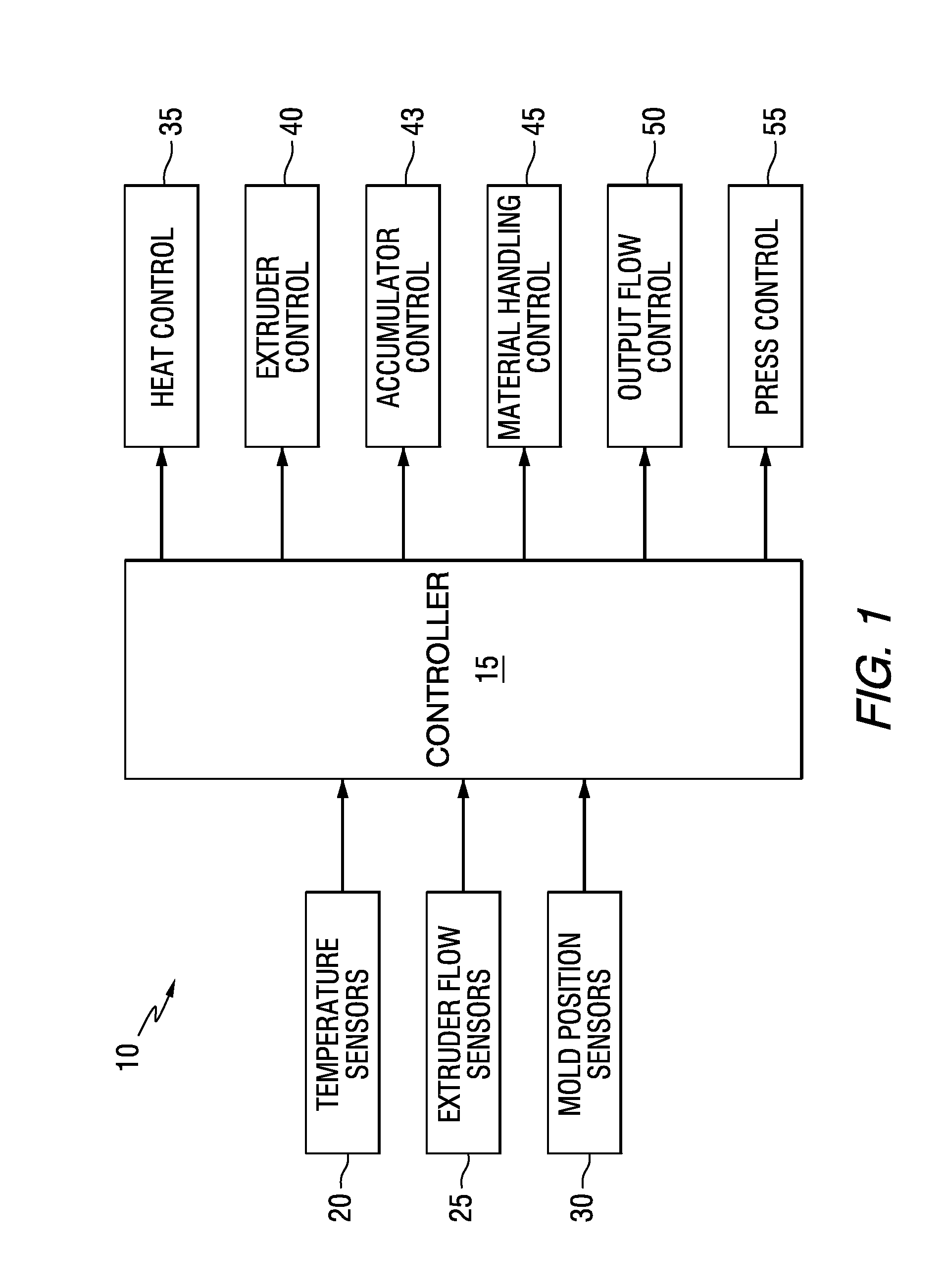
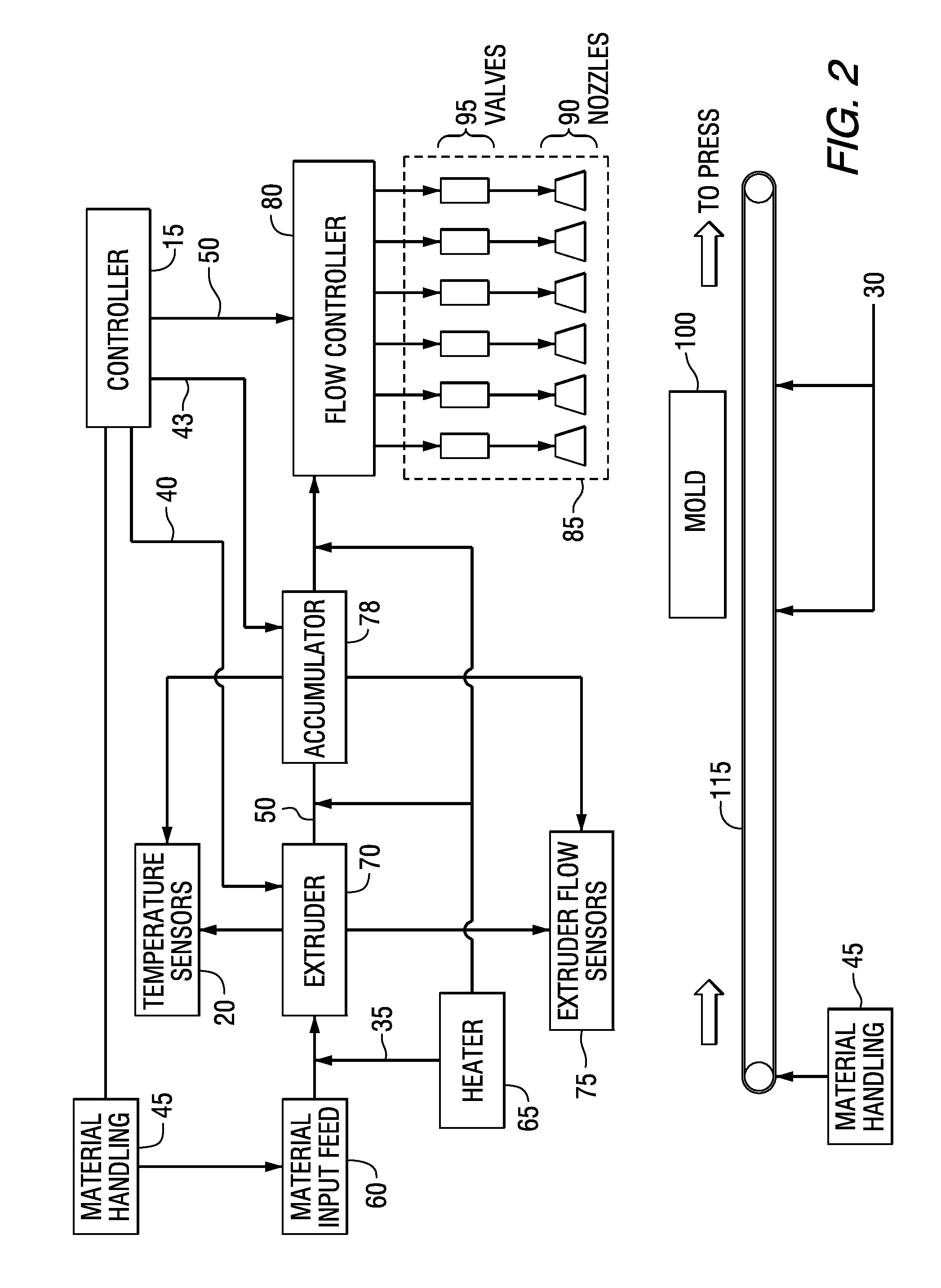
[0030]Referring now to FIGS. 1 and 2, the system 10 is controlled by central controller 15. Central controller 15 is comprised of a computing device of a known type, having processor, memory and I / O capabilities. Central controller 15, in addition to human input devices for the purpose of programming and monitoring, has inputs from various sensors throughout system 10. These include temperature sensors 20, extruder flow sensors 25 and, optionally, mold position sensors 30. It is to be specifically noted that system 10 may be adapted for single mold use, in which a single mold is manually positioned for filling and no conveyor or other transport system is necessary. Extruder flow sensors 25 may additionally be positioned in conjunction with an optional accumulator 78 for downstream flow information.

[0031]Central controller 15 includes a variety of outputs, in addition to those intended for human monitoring, programming and control. Heat control circuit 35 is utilized to maintain adeq...


PUM

PropertyMeasurementUnit
molten plasticaaaaaaaaaa
surface featureaaaaaaaaaa
temperatureaaaaaaaaaa

Abstract

A material handling and mold filling system is provided which directs the flow of molten plastic material from an extruder and allocates the molten material to a plurality of nozzles through the use of independently operated, variable valves. The system therefore provides independent streams of molten plastic material having variable temperatures and flow rates or volumes to particular sections or regions of the mold. This independent temperature or flow of molten plastic material facilitates the complete, rapid and accurate filling of the molds, reducing turbulence and other temperature or flow-related imperfections in the finished components. A multiphase material handling system is also disclosed for expeditious sequential and simultaneous filling and pressing of the mold and extracting the completed component from the system.

Description

BACKGROUND OF THE INVENTION[0001]1. Field of the Invention[0002]The present invention relates to a plastic molding apparatus and method. More particularly, the present invention relates to a suspended multi-port flow controller and apparatus which dispenses and disperses molten plastic material in a preselected manner to facilitate complete and rapid filling of an open product mold.[0003]2. Description of the Prior Art[0004]Molded plastic components are generally formed by creating a mold having a hollow cavity of the desired configuration. The mold sections may be opened and the lower portion may be filled with molten plastic material in the form of a fillet, or the mold may closed and the molten plastic material injected into the mold. The molten material may be injected under pressure, such as in injection molding; pressed within a split mold, such as in compression molding; or drawn by vacuum into the mold, such as in vacuum forming, for final shaping and cooling into the finish...

Claims


Application Information

Patent Timeline
Patent Type & Authority Applications(United States)
IPC IPC(8): B29C31/10B29C48/345B29C48/92
CPCB29C31/10B29C31/042B29C47/92B29C2947/92104B29C2947/92209B29C2947/92409B29C2947/926B29C2947/92704B29C2947/92904B29C48/92B29C2948/926B29C2948/92104B29C2948/92209B29C2948/92409B29C2948/92704B29C2948/92904B29C45/13B29C2043/3433B29C2043/046B29C31/047B29C2045/279B29C2043/5875B29C31/06B29C43/04
Inventor ROSAN, ARNON
Owner SIGNATURE SYST GRP LLC
Why Eureka
Try Eureka