Phase-locked loop with loop gain calibration, gain measurement method, gain calibration method and jitter measurement method for phase-locked loop

a phase-locked loop and gain calibration technology, which is applied in the direction of noise figure or signal-to-noise ratio measurement, pulse automatic control, instruments, etc., can solve the problems of affecting the achievement of best noise bandwidth, affecting the actual circuit characteristics of the original design value, and consuming more power

Inactive Publication Date: 2014-03-20
NAT CHIAO TUNG UNIV
View PDF2 Cites 39 Cited by
  • Summary
  • Abstract
  • Description
  • Claims
  • Application Information

AI Technical Summary

Problems solved by technology

On the contrary, analog circuits have smaller voltage tolerance, larger leakage current and noise influence under the SoC environment, so as to increase the difficulty in designing a high-performance phase-locked loop.
Unfortunately, the above parameters are influenced by process variations, resulting in deviations of the actual circuit characteristics from the original design values, and hindering the achievement of best noise bandwidth.
This is not only time consuming, but also results in more power consumption.

Method used


Image

  • Phase-locked loop with loop gain calibration, gain measurement method, gain calibration method and jitter measurement method for phase-locked loop
  • Phase-locked loop with loop gain calibration, gain measurement method, gain calibration method and jitter measurement method for phase-locked loop
  • Phase-locked loop with loop gain calibration, gain measurement method, gain calibration method and jitter measurement method for phase-locked loop

Examples


first embodiment

[0025]FIG. 3 is a schematic diagram depicting the structure of a frequency synthesizer with loop gain calibration according to the present invention for illustrating the methods for measuring and calibrating the gain of a PLL, and more preferably, a non-integer all digital PLL.

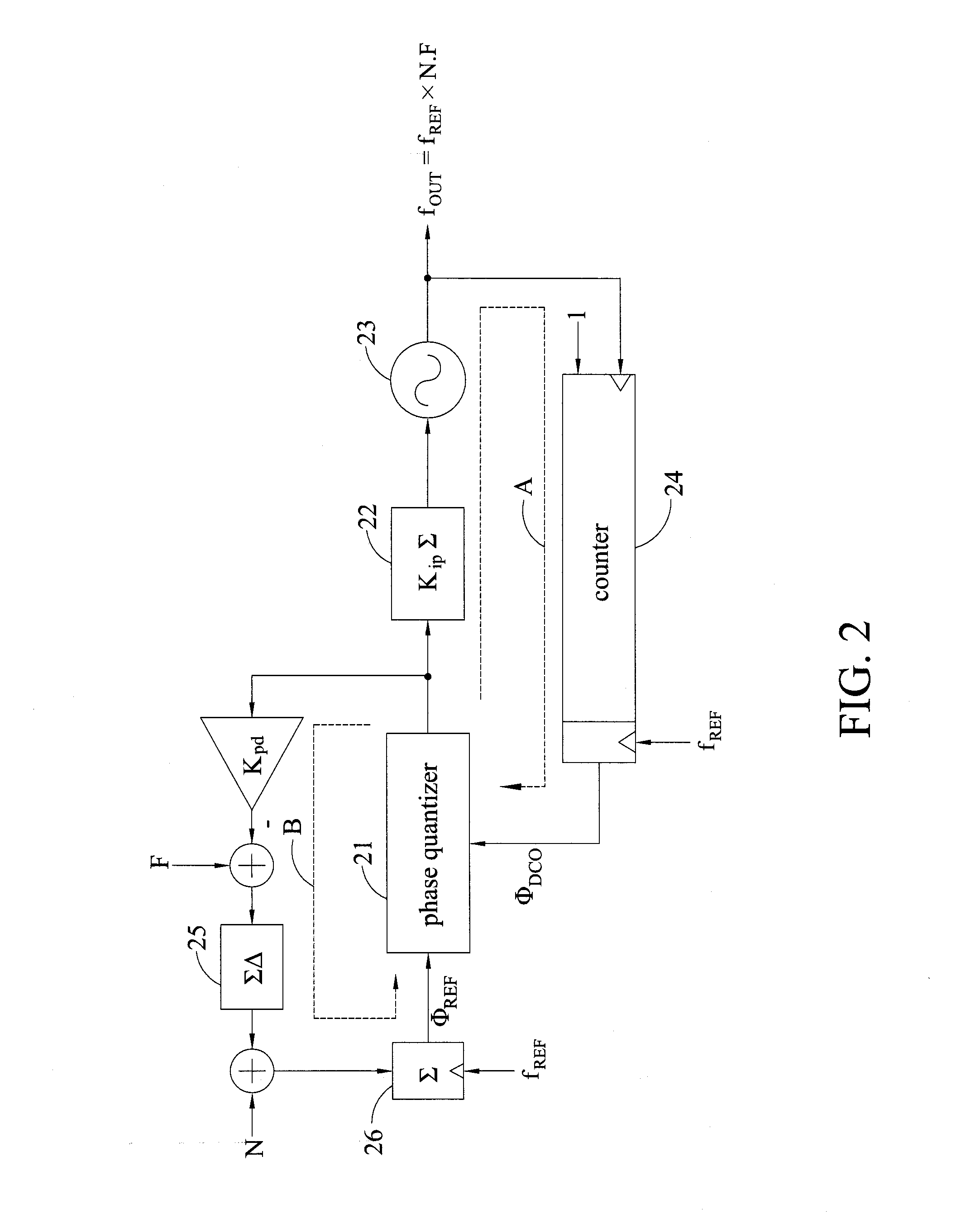
[0026]In FIG. 3, the frequency synthesizer with loop gain calibration includes a feedback phase integral path A, a reference phase integral path B, a phase quantizer 21, and a gain estimator 27.

[0027]The feedback phase integral path A includes a loop filter 22, an oscillator 23 receiving the product of a frequency tuning word having a varying code (AC) multiplied by a gain correcting factor ({circumflex over (K)}DCO[n])−1, and a counter 24 calculating the rising edges of the output frequency of the oscillator 23 (fOUT) and outputting excess feedback phase information (ΦDCO).

[0028]The reference phase integral path B includes a delta-sigma modulator 25 receiving the sum of a fractional frequency tuning word (F) ...

second example

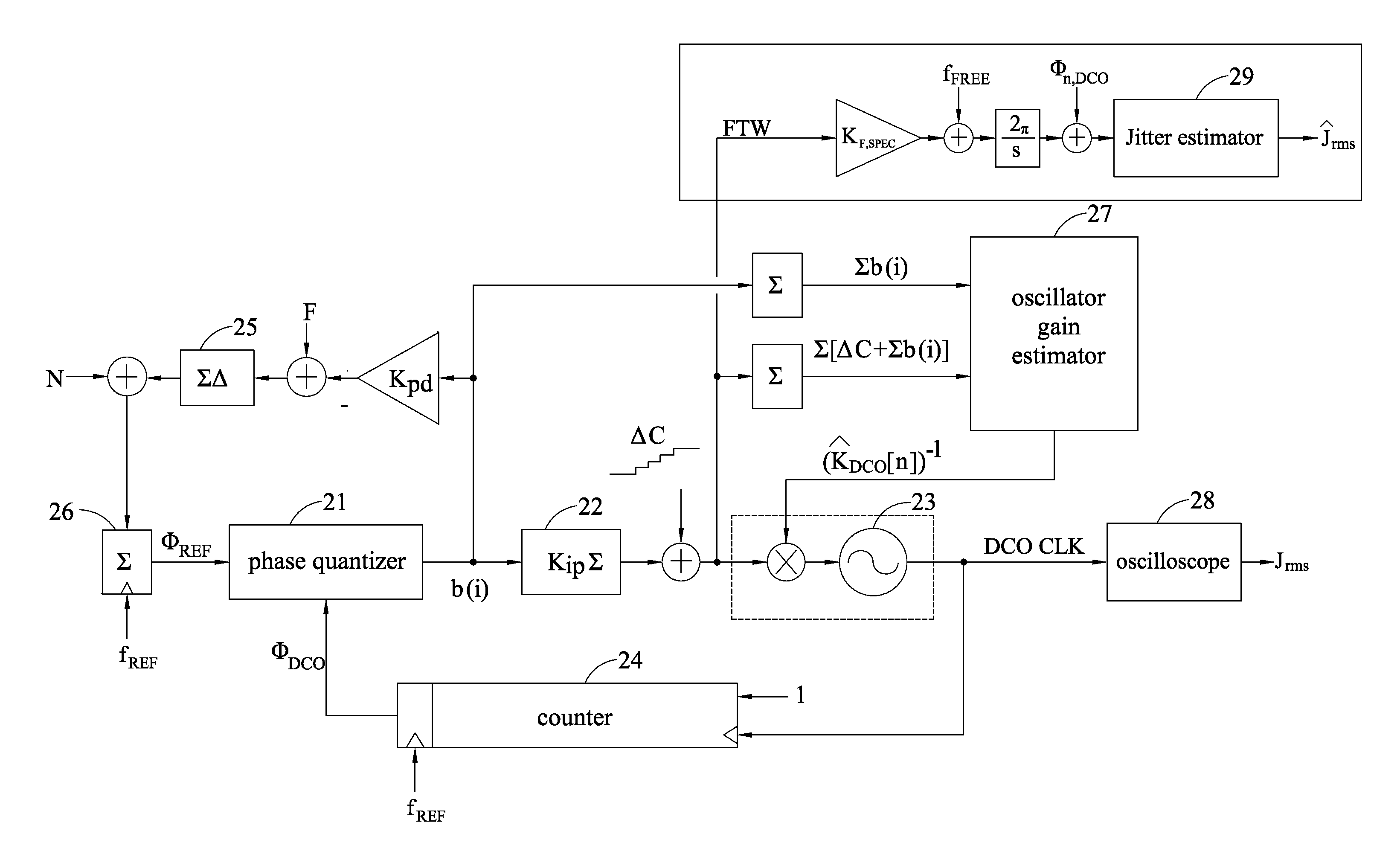
[0051]Clock jitter is an important indicator for assessing the merits of a phase-locked loop. Traditionally, the performance of a phase-locked loop is mostly assessed by measuring clock jitter using an external instrument, but with the increase in the output frequency of the phase-locked loop, the cost of the measurement instrument greatly increases. Therefore, a method for estimating the amount of jitter on the chip involves calculating jitter noise by using the frequency tuning word (FTW) at the input end of the oscillator, which lowers the measuring frequency from the output frequency down to the reference frequency. This considerably reduces the cost of the measurement instrument.

[0052]In an all digital phase locked loop (ADPLL) shown in FIG. 7 similar to that described above, the bandwidth is determined by the known parameter of the digital loop (weight of the loop filter 22 (Kip)), the weight Kpd of the reference phase integral path B, the maximum resolution (Mdsm) of the delt...


PUM


Abstract

The invention provides a phase-locked loop with loop gain calibration and methods for measuring an oscillator gain, gain calibration and jitter measurement for a phase-locked loop. The method for measuring an oscillator gain of a phase-locked loop includes the steps of providing a varying code at an input end of the oscillator; outputting excess reference phase information by a reference phase integral path and outputting excess feedback phase information based on the varying code by a feedback phase integral path; and obtaining an estimated gain information of the oscillator based on the excess reference phase information and the excess feedback phase information.

Description

FIELD OF THE INVENTION[0001]The present invention relates to a phase-locked loop with loop gain calibration, a gain measurement method, a gain calibration method and a jitter measurement method for a phase-locked loop.BACKGROUND OF THE INVENTION[0002]A frequency synthesizer plays a very important role in current communication systems, which may be wired or wireless receivers, mobile phones or satellite receivers. A frequency synthesizer is used for generating a periodic signal having known frequency and phase relationships with a reference signal. This generated clock signal can be used as a clock source for a processor in a high-speed data transfer interface, a sampling clock for an analog-to-digital converter, or a local oscillator signal in a radio transmitter for frequency mixing. Various frequency synthesis technologies have been proposed over years, such as phase-locked loop (PLL), direct digital frequency synthesis (DDFS), frequency mixing, and the like. In these frequency sy...

Claims


Application Information

Patent Timeline
Patent Type & Authority Applications(United States)
IPC IPC(8): H03L7/08G01R25/00
CPCG01R25/00H03L7/08G01R31/31709H03L7/099H03L7/16H03L2207/50
Inventor CHEN, WEI-ZENCHUANG, SHU-CHIN
Owner NAT CHIAO TUNG UNIV
Why Eureka
Try Eureka