Systems and methods for voltage control and current control of power conversion systems with multiple operation modes

a power conversion system and voltage control technology, applied in the field of integrated circuits, can solve the problems that the power conversion system b>100/b> often does not have satisfactory efficiency, and achieve the effects of improving system efficiency, reducing switching loss, and improving overall efficiency of the power conversion system

Active Publication Date: 2014-03-20
ON BRIGHT ELECTRONICS SHANGHAI
View PDF3 Cites 124 Cited by
  • Summary
  • Abstract
  • Description
  • Claims
  • Application Information

AI Technical Summary

Benefits of technology

[0022]Many benefits are achieved by way of the present invention over conventional techniques. Certain embodiments of the present invention provide systems and methods to employ multiple operation modes so that a power conversion system operates in a discontinuous conduction mode under no/light load conditions, operates in a quasi-resonant mode under medium load conditions, and operates, under full/heavy load conditions, in a continuous conduction mode for a low line input voltage or in the quasi-resonant mode for a high line input voltage in order to improve the overall efficiency of the power conversion system. Some embodiments of the present invention provide systems and methods to operate the power conversion system in a valley switching mode for a high line input voltage to reduce the switching loss and improve the system efficiency. Certain embodiments of the present invention provide systems and methods to operate the power conversi

Problems solved by technology

However, when operating in a single mode, the power conversion system 100

Method used


Image

  • Systems and methods for voltage control and current control of power conversion systems with multiple operation modes
  • Systems and methods for voltage control and current control of power conversion systems with multiple operation modes
  • Systems and methods for voltage control and current control of power conversion systems with multiple operation modes

Examples


Embodiment Construction

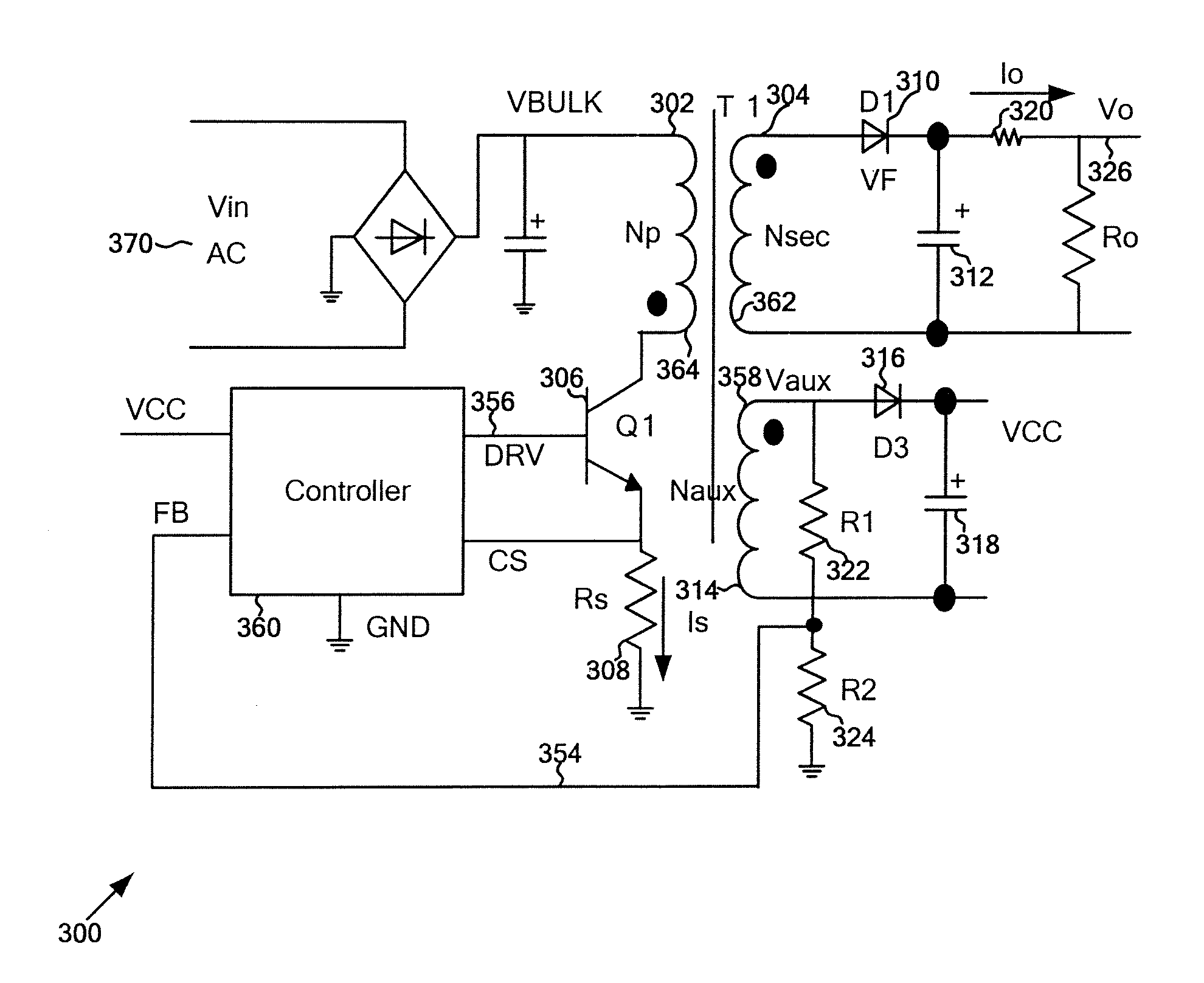
[0040]The present invention is directed to integrated circuits. More particularly, the invention provides systems and methods for voltage regulation and current regulation. Merely by way of example, the invention has been applied to a power conversion system. But it would be recognized that the invention has a much broader range of applicability.

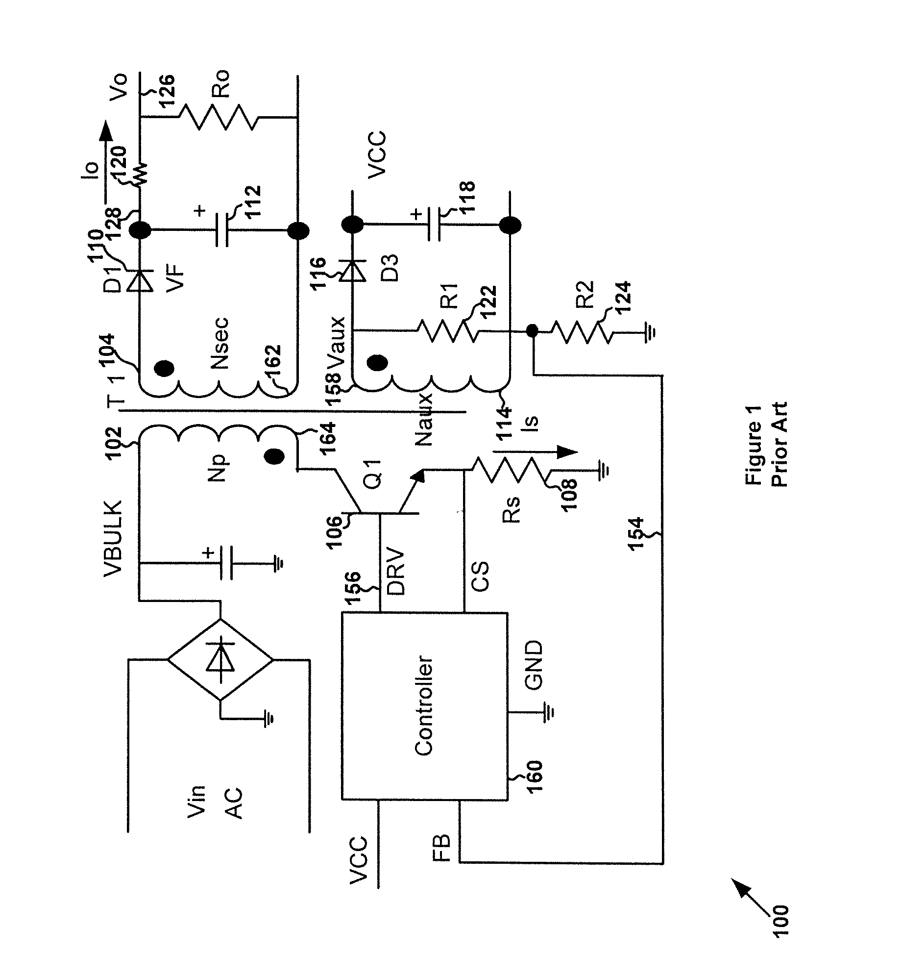
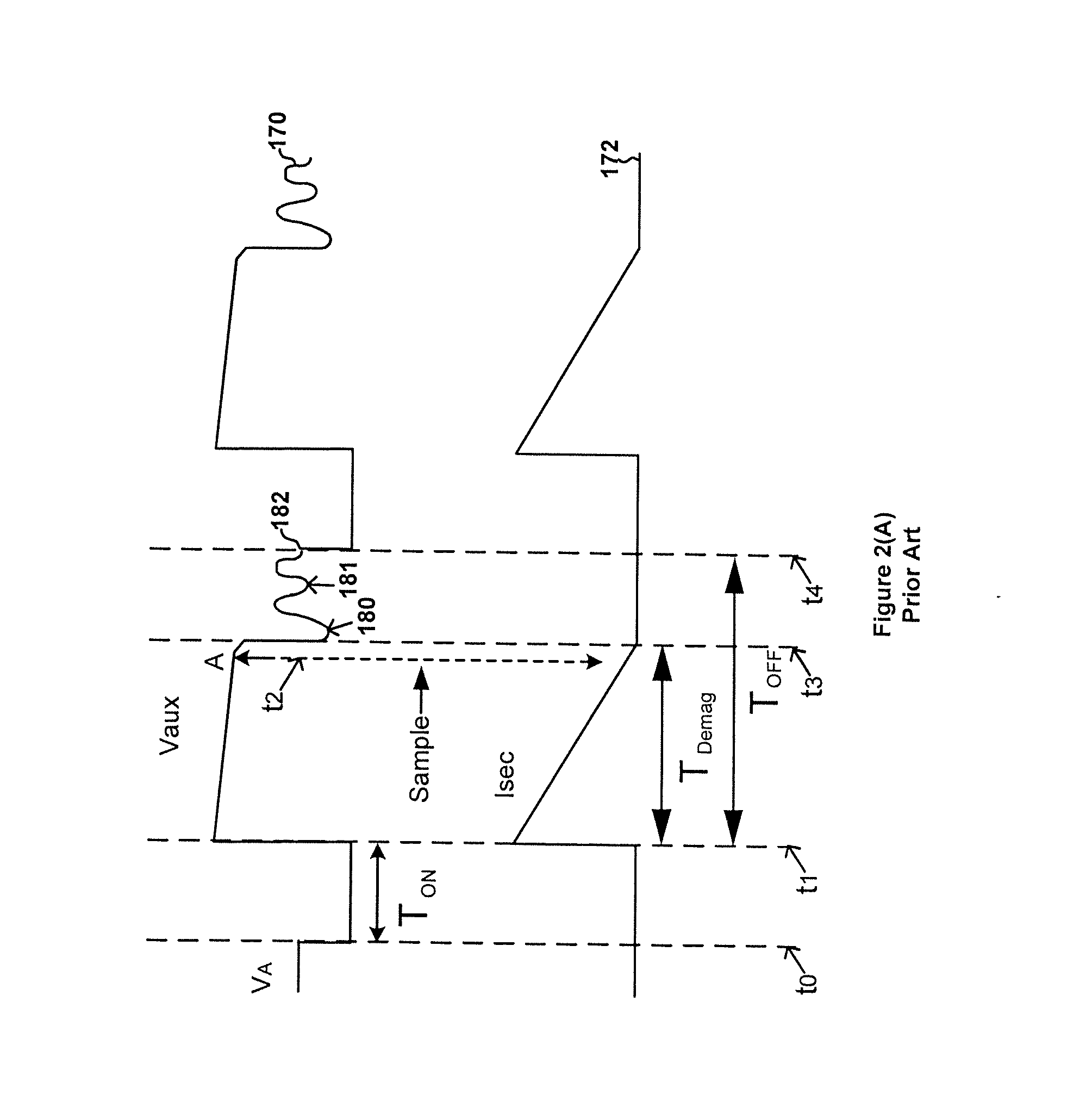
[0041]Referring to FIG. 1, power loss in the power conversion system 100 often includes a switching loss and a conduction loss. The conduction loss usually is associated with an on-resistance of the power switch 106. For example, when the power conversion system 100 receives a high line input voltage, the switching loss contributes more to the power loss than the conduction loss. In another example, when the power conversion system 100 receives a low line input voltage, the conduction loss contributes more to the power loss than the switching loss if the output load is full / heavy. Accordingly, multiple operation modes can be implemented in o...


PUM


Abstract

System and method for regulating a power conversion system. A system controller for regulating a power conversion system includes an operation-mode-selection component and a driving component. The operation-mode-selection component is configured to receive a first signal related to an output load of the power conversion system and a second signal related to an input signal received by the power conversion system and output a mode-selection signal based on at least information associated with the first signal and the second signal. The driving component is configured to receive the mode-selection signal and generate a drive signal based on at least information associated with the mode-selection signal, the driving signal corresponding to a switching frequency.

Description

1. CROSS-REFERENCES TO RELATED APPLICATIONS[0001]This application claims priority to Chinese Patent Application No. 201210342097.5, filed Sep. 14, 2012, incorporated by reference herein for all purposes.2. BACKGROUND OF THE INVENTION[0002]The present invention is directed to integrated circuits. More particularly, the invention provides systems and methods for voltage regulation and current regulation. Merely by way of example, the invention has been applied to a power conversion system. But it would be recognized that the invention has a much broader range of applicability.[0003]FIG. 1 is a simplified diagram showing a conventional flyback power conversion system. The power conversion system 100 includes a primary winding 102, a secondary winding 104, an auxiliary winding 114, a power switch 106, a current sensing resistor 108, two rectifying diodes 110 and 116, two capacitors 112 and 118, three resistors 120, 122 and 124, and a system controller 160. For example, the power switch ...

Claims


Application Information

Patent Timeline
IPC IPC(8): H02M3/335
CPCH02M3/33507H02M1/0032Y02B70/10H02M3/335H02M1/0009
Inventor LIN, YUANHUANG, XIAOMINLUO, QIANGFANG, LIEYI
Owner ON BRIGHT ELECTRONICS SHANGHAI
Why Eureka
Try Eureka