Two-channel directional antenna and a radar level gauge with such an antenna

a level gauge and antenna technology, applied in waveguide horns, instruments, reradiation, etc., can solve the problems of significant cost increase, affecting signal strength and thus sensitivity requirements, and not desirable to implement a two-antenna system in commercial rlg-systems, etc., and achieve adequate performance

Active Publication Date: 2014-03-27
ROSEMOUNT TANK RADAR
View PDF23 Cites 9 Cited by
  • Summary
  • Abstract
  • Description
  • Claims
  • Application Information

AI Technical Summary

Benefits of technology

[0008]It is an object of the present invention to provide a dual channel antenna with performance adequate for use in a radar level gauge.
[0009]According to a first aspect of the present invention, this and other objects are achieved by a level gauge for determining a filling level of a product in a tank, the radar level gauge comprising a transceiver for transmitting an electromagnetic transmit signal and receiving an echo signal, processing circuitry connected to the transceiver and adapted to determine the filling level based on a relationship between the transmit signal and the echo signal, and a two-channel, directional antenna having an antenna aperture adapted to emit electromagnetic energy in a direction of radiation. The antenna is connected to the transceiver and arranged to emit the transmit signal into the tank towards a surface of the product, and to receive the echo signal resulting from a reflection of the transmit signal in the product surface, wherein the antenna comprises an antenna aperture intended to face the product surface. The arrangement further comprises a partition wall dividing the antenna into a first partition for emitting the transmit signal and a second partition for receiving the echo signal, the partition wall having an outer potion located downstream in the direction of radiation. The arrangement further comprises an electromagnetic coupling arrangement comprising a first waveguide feeder arranged to couple the transmit signal from the transceiver into the first antenna partition, and a second waveguide feeder arranged to couple the echo signal from the second antenna partition to the transceiver, The partition wall includes an electromagnetic de-coupling structure, connected to the outer portion of said partition wall and arranged to reduce any leakage of electromagnetic energy from said transmit signal into said echo signal.
[0010]The electromagnetic de-coupling structure according to the present invention ensures that the leakage of transmit signal into the received signal is reduced to a satisfactory level.
[0013]According to one embodiment, the partition wall includes a protruding lip portion extending outside the antenna opening, and the electromagnetic de-coupling structure is arranged at least partly on this protruding lip portion. The coupling between the first and second antenna portions is thus significantly reduced by means of the protruding lip portion, extending a distance outside the antenna mouth. The coupling between the two partitions is thus reduced not only inside the antenna, but also a distance outside the antenna opening.
[0014]The electromagnetic de-coupling structure may further comprise a dielectric lens arranged at the aperture of the antenna. Such a lens may also compensate for any disturbance in the phase front of the antenna transmission caused by the partition wall and any protruding lip portion.

Problems solved by technology

Also other factors, such as interference and impurities on the antenna affect the signal strength and thus the sensitivity requirements.
However, for practical reasons, it is not desirable to implement a two-antenna system in commercial RLG-systems.
First of all there would be a significant cost increase, making such a system unattractive for the main market.
Also for this reason, a two-antenna system is less attractive, at least if each antenna requires a separate opening in the tank wall.
However, existing prior art solutions have not been found adequate for use in radar level gauges.

Method used


Image

  • Two-channel directional antenna and a radar level gauge with such an antenna
  • Two-channel directional antenna and a radar level gauge with such an antenna
  • Two-channel directional antenna and a radar level gauge with such an antenna

Examples


Embodiment Construction

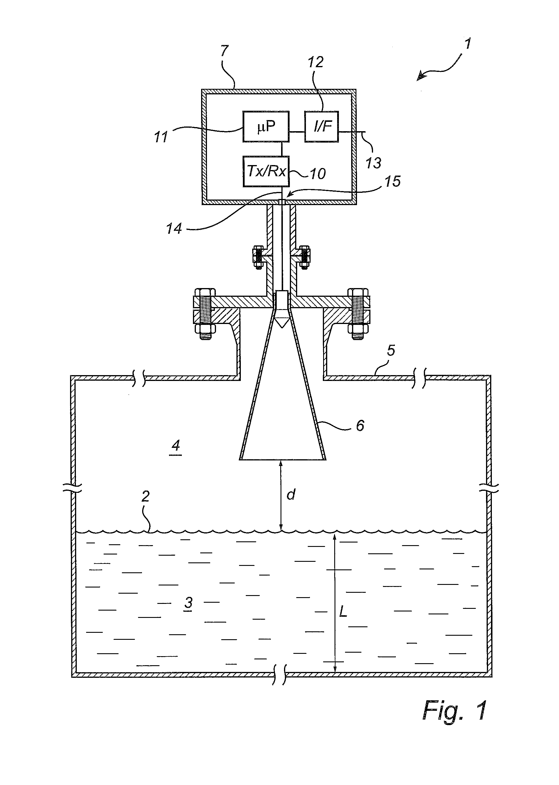
[0024]FIG. 1 shows a perspective view of a radar level gauge (RLG) 1, according to an embodiment of the present invention. The gauge 1 is arranged to perform measurements of a process variable in a tank 5, such as the level L of an interface 2 between two (or more) materials 3, 4 in the tank 5. Typically, the first material 3 is a content stored in the tank, e.g. a liquid such as gasoline, but non liquid materials such as grain or pellets may also be detected. The second material 4 is typically air or some other atmosphere present in the tank above the first material 3. The RLG will enable detection of the distance d to the interface 2 in the tank, and this distance may be used to calculate the level L, or some other process variable of interest.

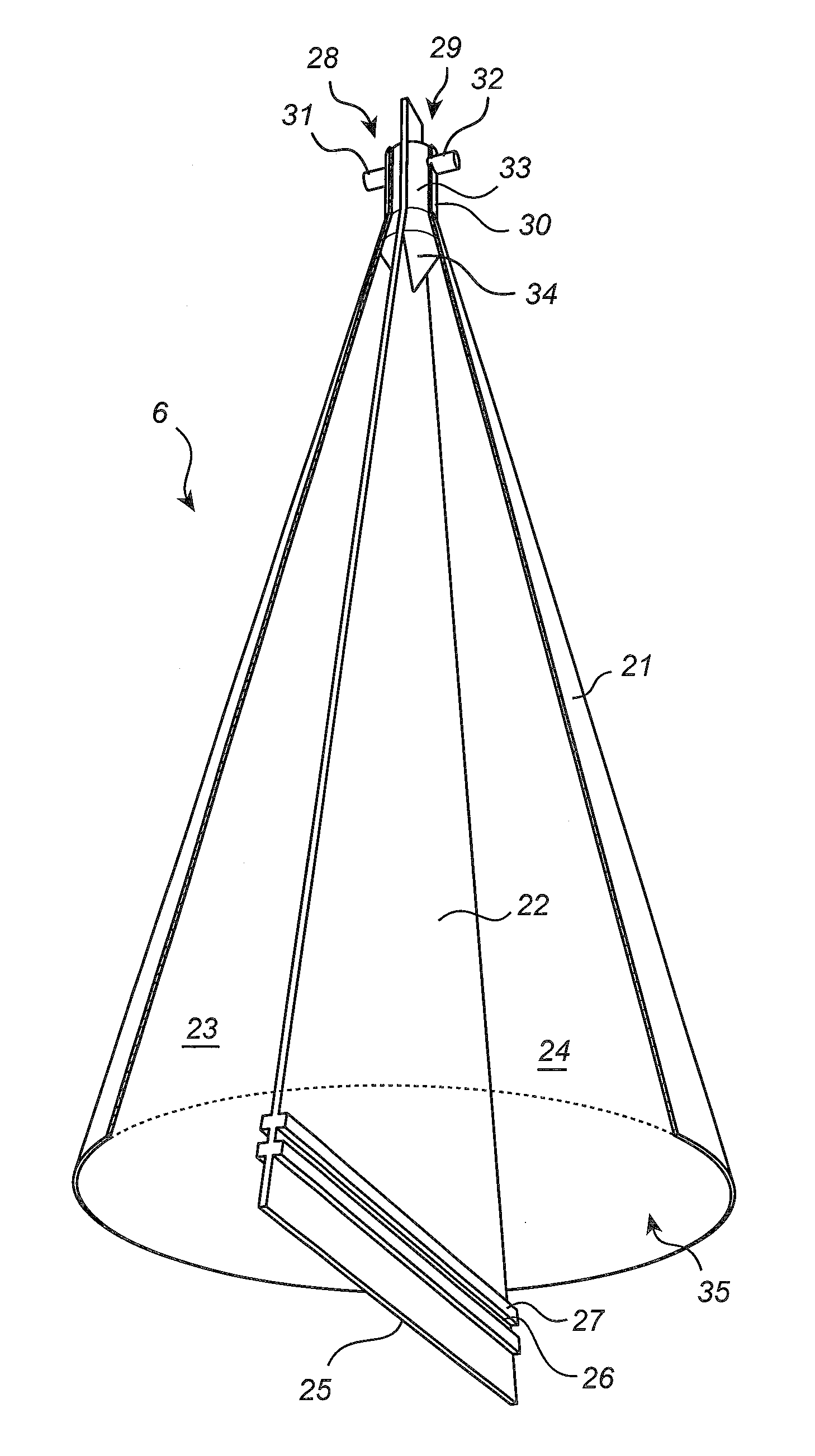
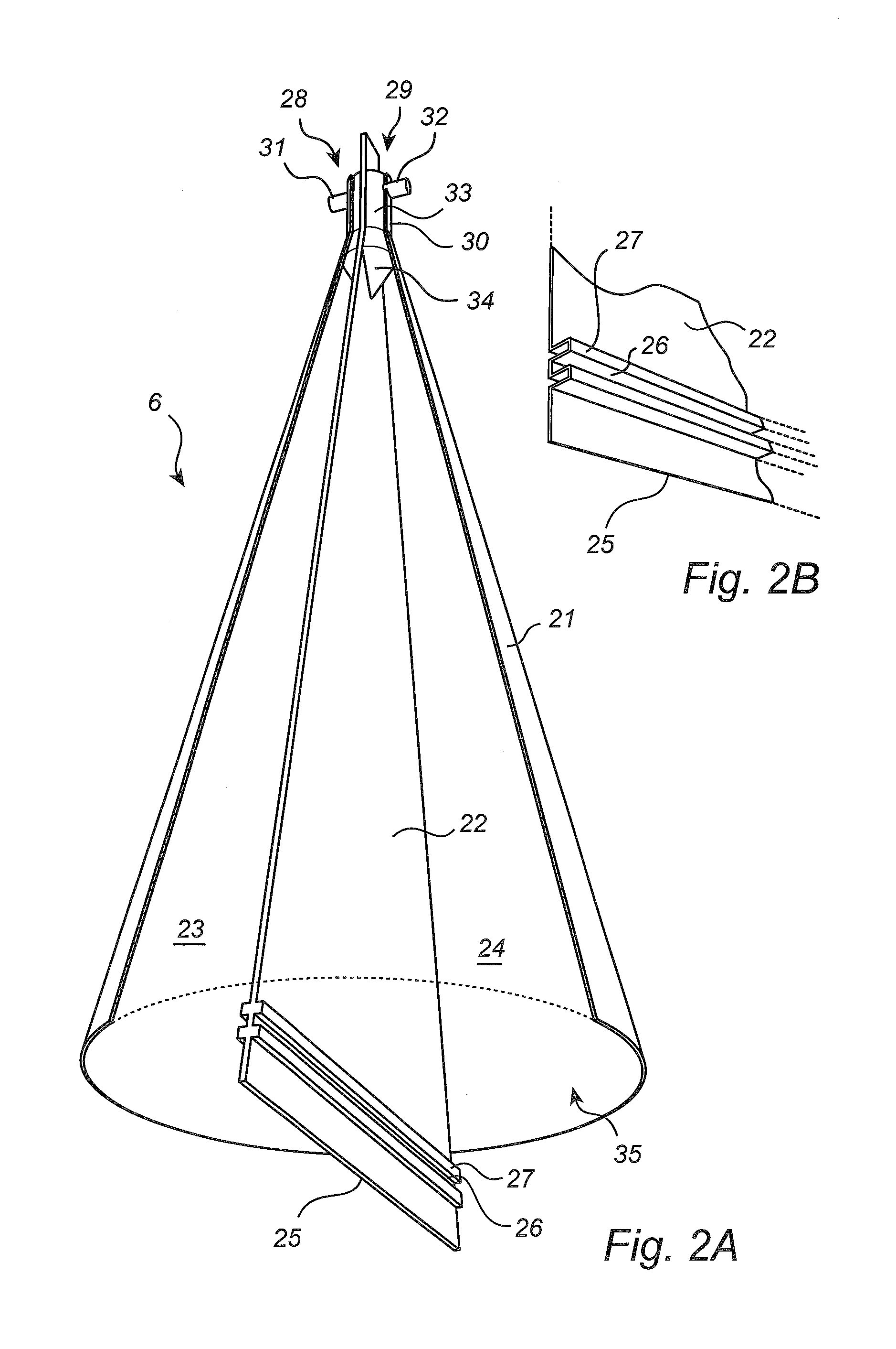
[0025]The RLG 1 further comprises a free radiating directional antenna 6 in the top of the tank for emitting electromagnetic transmit signals into the tank 5 and for receiving electromagnetic echo signals from the tank. The RLG 1 further com...


PUM


Abstract

A two-channel directional antenna for use in a radar level gauge. The antenna comprises a partition wall the antenna into a first partition for emitting an electromagnetic transmit signal, and a second partition for receiving an electromagnetic echo signal, the partition wall having an outer potion located downstream in a direction of radiation of the antenna. The partition wall comprises an electromagnetic de-coupling structure, which is arranged to reduce any leakage of electromagnetic energy from the transmit signal into the echo signal.The electromagnetic de-coupling structure according to the present invention ensures that the leakage of transmit signal into the received signal is reduced to a satisfactory level.

Description

FIELD OF THE INVENTION[0001]The present invention relates to a level gauge system using electromagnetic waves for measuring a filling level of a surface of a product in a container.BACKGROUND OF THE INVENTION[0002]Radar level gauges (RLGs) are suitably used for making non-contact measurements of the level of products such as process fluids, granular compounds and other materials contained in a tank. An example of such a radar level gauge can include a transceiver for transmitting and receiving electromagnetic waves, an antenna arranged to direct electromagnetic waves towards the surface and to return electromagnetic waves reflected by the surface to the transceiver, and processing circuitry adapted to determine the filling level based on a relation between electromagnetic waves transmitted and received by the transceiver.[0003]In some applications, e.g. level detection of solids, such as grain, very high sensitivity is required due to the weak reflection from the surface. Also other...

Claims


Application Information

Patent Timeline
Patent Type & Authority Applications(United States)
IPC IPC(8): G01S13/08
CPCG01S13/08G01S13/88H01Q1/225H01Q13/02H01Q19/08G01F23/284G01S7/03H01Q9/28
Inventor WESTERLING, JAN
Owner ROSEMOUNT TANK RADAR
Why Eureka
Try Eureka