Subsea pressure booster

a technology of subsea pressure booster and compressor, which is applied in the direction of positive displacement liquid engine, piston pump, liquid fuel engine, etc., can solve the problems of low reliability and robustness of equipment, large dimensions and weight of subsea vsd, and difficulty in installation and retrieval

Active Publication Date: 2014-03-27
AKER SOLUTIONS AS
View PDF11 Cites 7 Cited by
  • Summary
  • Abstract
  • Description
  • Claims
  • Application Information

AI Technical Summary

Benefits of technology

[0036]For a compressor the atmosphere of the compartment for gear and motor in theory should be kept protected from contaminant by having a flow velocity of an inert gas through a seal higher than the diffusion velocity of the contaminants. If the total atmosphere volume of the motor and gear included gas cooler and piping is 2 m2, it is assumed that a supply of inert gas, e.g. dry nitrogen or dry methane, at a rate that results in some few volume exchanges per year is enough to protect the materials from being damaged

Problems solved by technology

However, while subsea processing equipment has gained acceptance over the resent years for being a realistic option, there is more reluctance against electric and electronic equipment, i.e. a perception of that this type of equipment will have low reliability and robustness.
A SVSD (subsea VSD) will also be large in dimensions and weight and therefore not easy to install and retrieve.
The cost will also be high.
However, the cost of a feasible subsea VSD for a motor of 10 MW can indicatively be 100 MNOK, the weight about 100 tons, the height about 11 m and the diameter about 3 m. But a worse problem is the risk of limited reliability of a subsea VSD.
Even though the subsea VSD contains top quality components, each of very high quality and reliability, the large number of components and the complexity of the structure result in a total subsea VSD reliability that may be a significant problem.

Method used


Image

  • Subsea pressure booster
  • Subsea pressure booster
  • Subsea pressure booster

Examples


Embodiment Construction

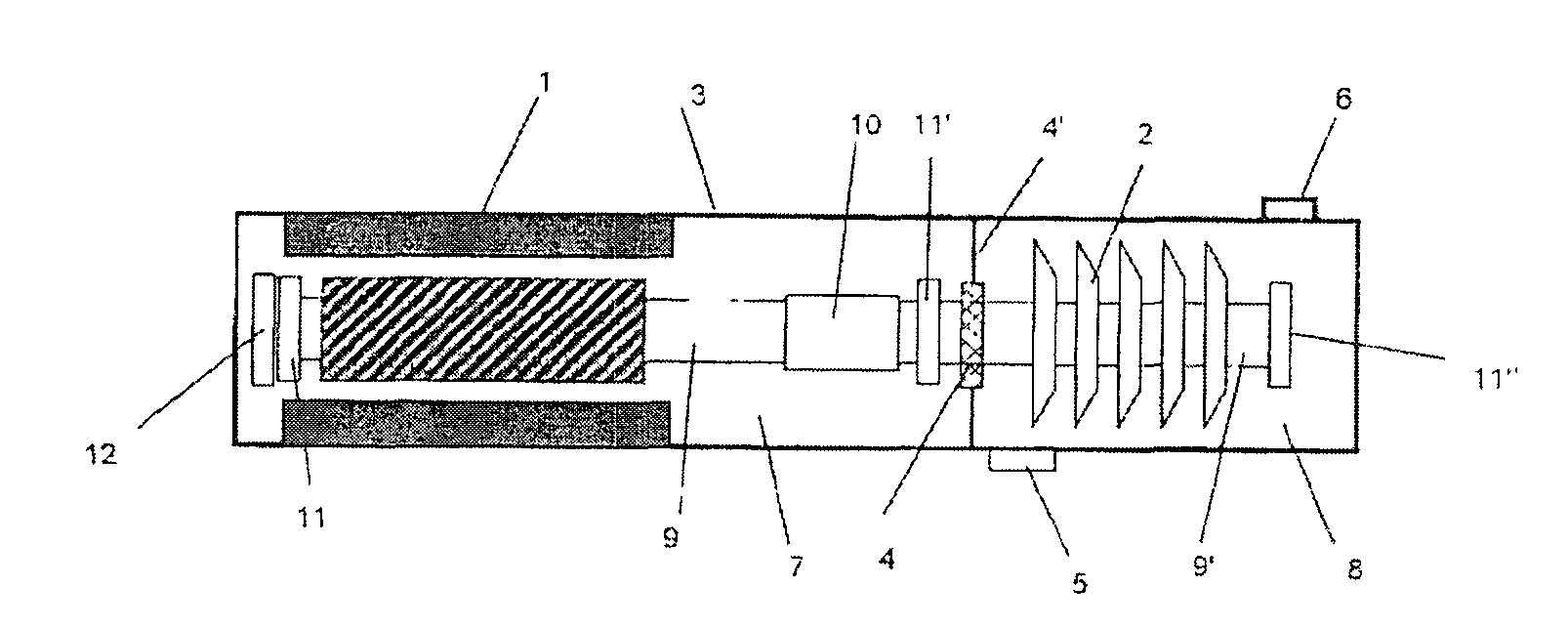
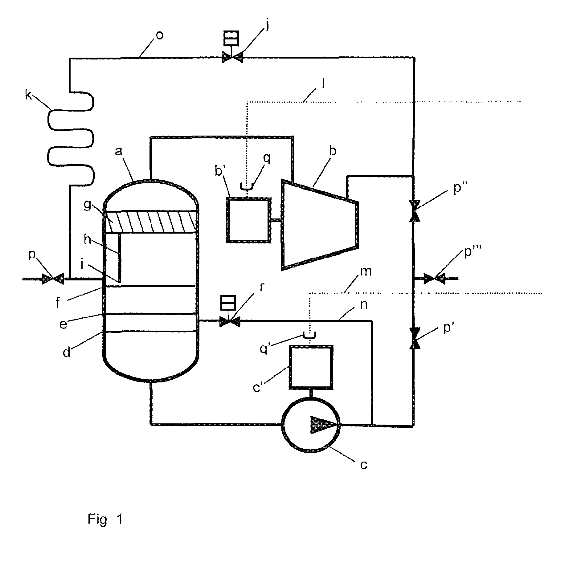
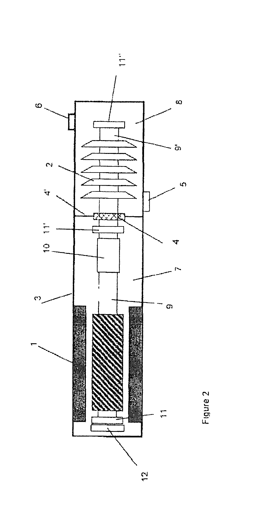
[0045]In the following the invention in several embodiments will be illustrated and explained by figures. Reference is made to Table 2 for understanding of FIG. 3-5. It shall be mentioned that only main components necessary for understanding of the invention are included in FIGS. 3-6.

TABLE 2Item #Explanation 1Motor 2Compressor or other turbomachine 3Pressure housing 4Shaft seal 4′Partition 5Compressor (or other turbomachine) inlet 6Compressor (or other turbomachine) outlet 7Compartment for motor and magnetic gear or low speedpart of the magnetic gear 8Compartment for compressor and high speed side of gear 9, 9′Shafts10Shaft coupling either rigid or flexible or common shaft forcompressor and motor11, 11′, 11″,Radial bearings11′″12, 12′Axial bearings13Magnetic gear14Low speed side of magnetic gear15High speed side of magnetic gear16Partition, diaphragm or shroud hermetically separating lowand high speed of gear17Pressure vessel or tank for nitrogen18, 18′Control valves19Pressure-Volum...


PUM


Abstract

Subsea turbomachine for boosting the pressure of petroleum fluid flow from subsea petroleum productions wells or systems, comprising an electric motor and a compressor or pump driven by the electric motor, a fluid inlet and a fluid outlet, distinctive that the turbomachine comprises a pressure housing common for the electric motor or stator, and compressor, pump or rotor; a magnetic gear inside the common pressure housing for operative connection between the motor or stator and compressor, pump or rotor; and a partition inside the common pressure housing, arranged so as to separate a motor or stator compartment from a compressor, pump or rotor compartment.

Description

FIELD OF THE INVENTION[0001]The present invention relates to pressure boosting. More specifically, the invention relates to compressors and pumps, particularly subsea compressors and pumps, including multiphase pumps, for boosting the pressure of gas, multiphase or liquid from subsea petroleum production wells or systems. In the follow will be used a common term: Pressure boosters; for turbo machines such as compressors, multiphase pumps and liquid pumps.BACKGROUND OF THE INVENTION AND PRIOR ART[0002]The pressure of a petroleum reservoir, particularly a gas reservoir, decline rather rapidly during production. In order to maintain and prolong production from subsea reservoirs, often involving long transport through a pipeline of the produced fluid, pressure boosting is required.[0003]In FIG. 1 is illustrated the process of a subsea compression station. The rotating equipment is compressors and pumps. The rotational speed of pumps is typically in the range of 3000-4000 rpm while compr...

Claims


Application Information

Patent Timeline
Patent Type & Authority Applications(United States)
IPC IPC(8): F04D13/02F04D13/08F04D13/06
CPCF04D13/026F04D13/08F04D13/0653F04D1/06F04D13/024F04D13/086F04D17/122F04D25/026F04D25/0686F04D13/028F04D25/028F04D13/10F04D29/048F04D29/058F04D1/006F04D13/02F04D17/04F04D17/12F04D25/02F04D25/06
Inventor STINESSEN, KJELL OLAVERIKSEN, ASBJORN
Owner AKER SOLUTIONS AS
Why Eureka
Try Eureka