Sleeve type shaft kiln with power generation device

A power generation device, a sleeve-type technology, applied to the improvement of process efficiency, furnace, lime production, etc., can solve the problems of unfavorable carbon dioxide recovery and utilization, and achieve the effects of improving comprehensive economic benefits, reducing exhaust gas emissions, and improving thermal efficiency

Active Publication Date: 2014-10-29
SHIJIAZHUANG XINHUA IND FURNACE CO LTD
View PDF6 Cites 8 Cited by
  • Summary
  • Abstract
  • Description
  • Claims
  • Application Information

AI Technical Summary

Problems solved by technology

The carbon dioxide produced by the decomposition of limestone is a valuable resource. Since the decomposed carbon dioxide is mixed with the combustion flue gas, it is not conducive to the recovery and utilization of carbon dioxide.

Method used


Image

  • Sleeve type shaft kiln with power generation device
  • Sleeve type shaft kiln with power generation device

Examples


Embodiment 1

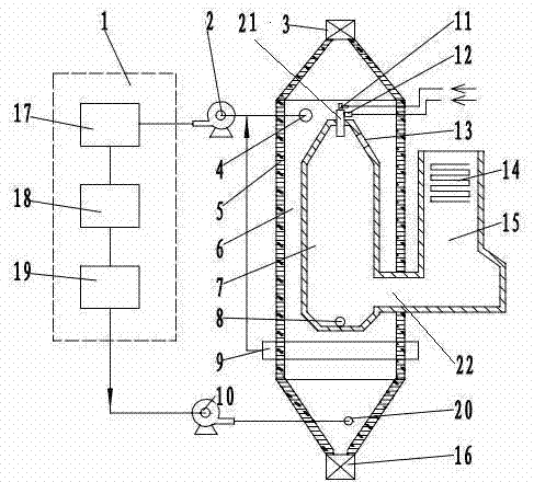
[0017] The sleeve type vertical kiln with power generation device of the present invention, as figure 1 As shown, it includes waste heat boiler 15, carbon dioxide treatment unit 1, power generation device, kiln body 5, induced draft fan 2, cooling fan 10, feeding equipment, air supply system and fuel supply system. The kiln body is provided with a material inlet 3, a material outlet 16, a decomposition gas outlet 4 and a cooling air inlet 20, and the cooling fan is connected to the cooling air inlet. The kiln body is divided into a preheating zone, a calcination zone and a cooling zone, and the upper part of the cooling zone is provided with a lower suction beam 9 . The power generation device includes a steam turbine and a generator set, and the steam turbine and the generator set are coaxially connected. The carbon dioxide processing unit 1 includes a carbon dioxide purification device 17 , a carbon dioxide cooling device 18 and a carbon dioxide storage tank 19 , and the ca...

Embodiment 2

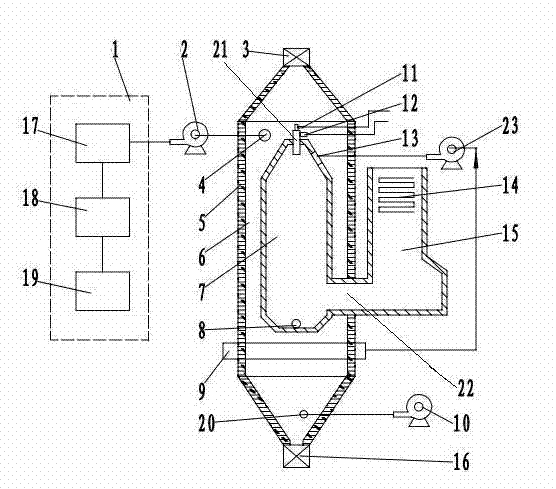
[0020] Another embodiment of the present invention is as figure 2 As shown, the primary air inlet 12 is connected with the blower, and the air is used as the combustion-supporting air. Cooling blower fan 10 inlet communicates with atmosphere, makes lime cooling wind with air. The decomposition gas outlet 4 is connected to the carbon dioxide treatment unit 1 through the induced draft fan 2, and the exhaust port of the waste heat boiler is connected to the waste gas discharge system. Carbon dioxide and pure oxygen produced by limestone decomposition enter the carbon dioxide treatment unit together with carbon dioxide produced by fuel combustion. The outlet of the lower suction beam 9 is connected to the secondary air inlet 13 through the carbon dioxide induced fan 23, and the high-temperature air after cooling the lime is used as the secondary combustion-supporting air for combustion in the combustion chamber. Other structures and operations are the same as in Embodiment 1.


PUM


Abstract

A sleeve type shaft kiln with a power generation device comprises a waste heat boiler, a carbon dioxide processing unit, the power generation device, a material supply device, an air supply system and a fuel supply system. A cooling zone of a kiln body is provided with a lower suction beam. The kiln body is internally provided with a combustion chamber, the combustion chamber has a cylinder structure, and the combustion chamber and the kiln body form an annular space. The upper part of the combustion chamber has a frustums structure, the top of the frustums is provided with a burn nozzle, and the side face of the frustums is provided with a secondary air inlet. The lower part of the combustion chamber is communicated with the waste heat boiler through a flue gas channel. A decomposition gas outlet is connected with the carbon dioxide processing unit through a draught fan, an outlet of the lower suction beam is connected to the secondary air inlet or an inlet of the draught fan, and an inlet of a cooling fan is connected with the carbon dioxide processing unit or is communicated with the atmosphere. A material in the kiln body is heated by heat conduction brick masonry in a flame isolation mode, so that the quality of the calcined product is improved, high-purity carbon dioxide is recycled, waste heat is used for power generation, thermal energy resources are fully utilized, and the comprehensive economic benefits of a lime kiln are increased.

Description

technical field [0001] The invention belongs to the technical field of industrial furnaces and kilns, and relates to a sleeve-type shaft kiln with a power generation device. Background technique [0002] Lime kiln waste heat recovery and utilization can save energy consumption, reduce lime production costs, and reduce pollutant emissions at the same time. Lime kiln is a large-scale high-energy-consuming device. With the rapid development of the national economy, the waste heat of industrial furnaces is very rich and has great potential for utilization. The iron and steel industry, calcium carbide industry, alumina industry and refractory material industry are major lime consumers. The rapid growth of the above industries has driven the rapid development of lime kilns. During the production process of large-scale active lime production line, the flue gas discharge temperature is high, about 240-260°C. Effective use of this part of the waste heat of the flue gas can reduce e...

Claims


Application Information

Patent Timeline
Patent Type & Authority Applications(China)
IPC IPC(8): C04B2/12C01B31/20F27D17/00C01B32/50
CPCY02P10/25Y02P20/129Y02P40/40
Inventor 贾会平
Owner SHIJIAZHUANG XINHUA IND FURNACE CO LTD
Why Eureka
Try Eureka