Electrical contact member

a contact member and electric technology, applied in the field of electric contact members, can solve the problems of reducing the reliability of the examining step or the operating rate of the connecting device for examination, the contact resistance value is not easily kept at a stable level, and the contact resistance value may be deteriorated into several hundred milliohms to several ohms, so as to prevent the contact resistance value from rising, reduce the adhesiveness, and prevent the effect of deterioration

Active Publication Date: 2014-04-03
KOBE STEEL LTD
View PDF11 Cites 4 Cited by
  • Summary
  • Abstract
  • Description
  • Claims
  • Application Information

AI Technical Summary

Benefits of technology

[0026]In the electrical contact member of the invention, a surface thereof that is to come into contact with a test subject is configured to be a carbon coating film containing Pd; and preferably the Pd content by percentage in the carbon coating film is appropriately controlled. Thus, the member makes it possible to have realized a low adhesiveness onto a test subject and have been restrained from rising in contact resistance even after subjected to repetitive contacting at a high temperature of about 85° C., or allowed to stand still in the atmosphere over a long term. Consequently, the member can keep stable electrical contacting over a long term.

Problems solved by technology

However, when a test subject is repeatedly examined therewith, the contact resistance value may be deteriorated into a value from several hundred milliohms to several ohms.
However, such an operation remarkably decreases the reliability of the examining step or the operating rate of the connecting device for examination.
Furthermore, the adhering solder or tin is being oxidized so that the contact resistance value is not easily kept at a stable level.

Method used


Image

  • Electrical contact member
  • Electrical contact member

Examples


example 1

[0059]In the present example, electrical contact members each having a carbon coating film containing any one of various metal elements shown in Table 1 were produced to examine the usefulness of Pd (effect of having decreased the contact resistance after the members were allowed to stand still at room temperature for a long period).

[0060]Specifically, in this example, as each contact probe, a spring built-in probe was used, the tip of which was divided into four regions. This contact probe (YPW-6XT03-047, manufactured by Yokowo Co., Ltd.) is a probe in which the topmost surface of a Be—Cu base is plated with Au—Co alloy.

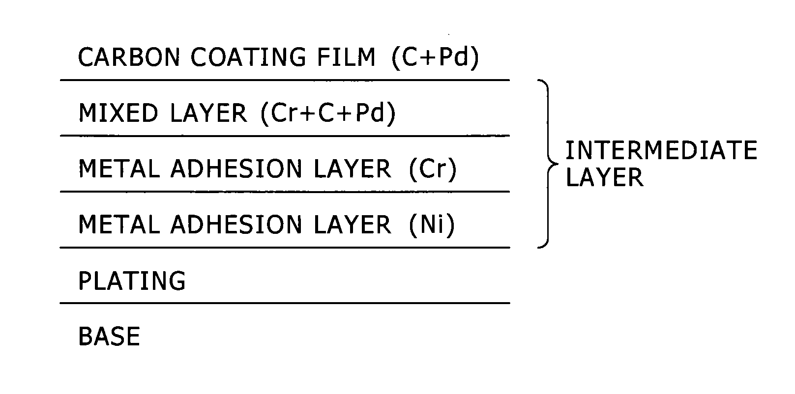
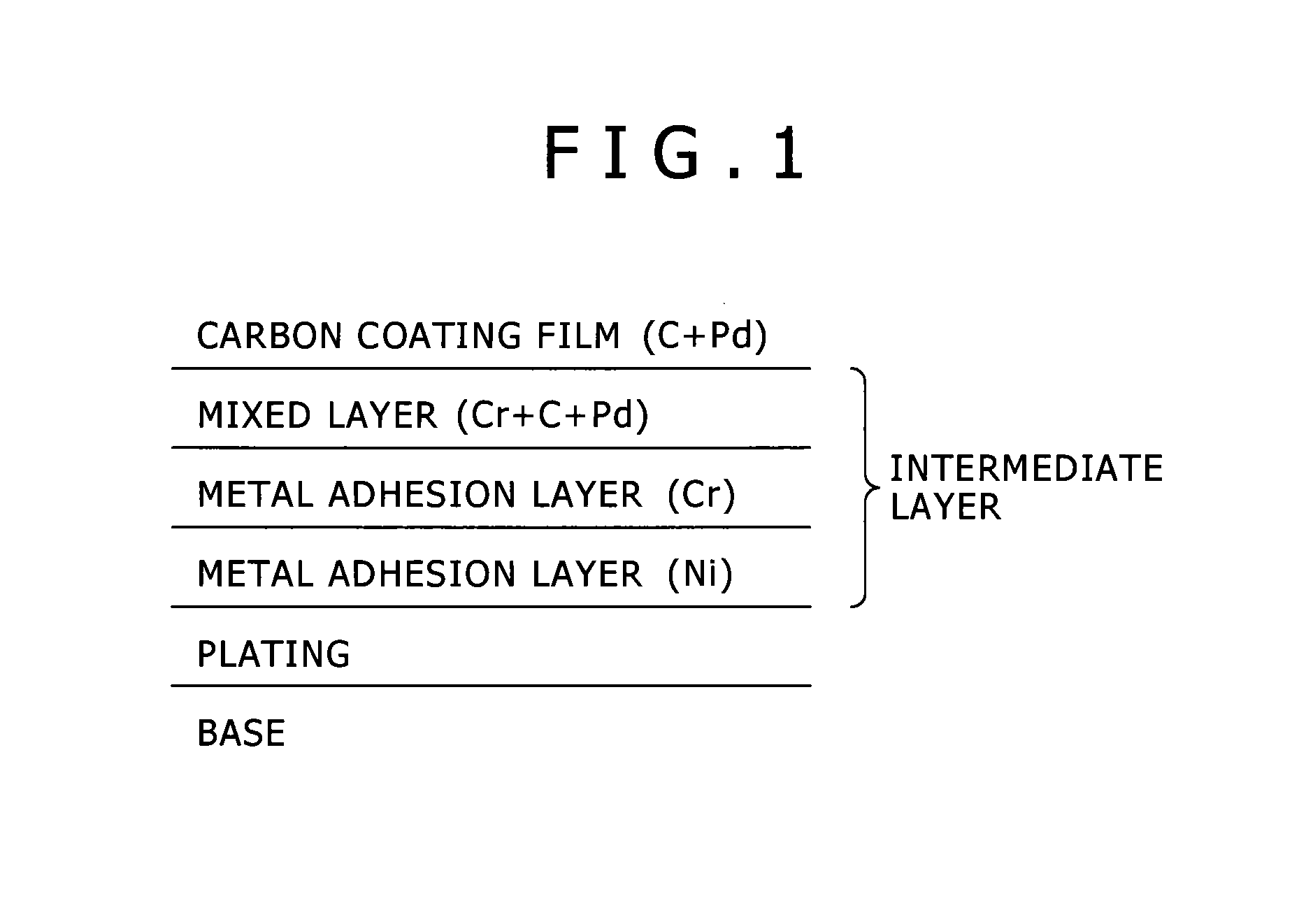
[0061]Next, a sputtering method was used to deposit an intermediate layer, for heightening the adhesiveness between the base and a carbon coating film to be formed thereon, and the carbon coating film successively.

[0062]Specifically, a DC magnetron sputtering apparatus was first used to deposit, onto the above-mentioned Au-based plating, Ni into a thickness of 50 nm...

example 2

[0083]In the present example, electrical contact members each having a carbon coating film containing any one of various metal elements shown in Table 2 were produced to examine the usefulness of Pd (effect of having decreased the contact resistance after the members were repeatedly subjected to contacting at high temperature).

[0084]Specifically, as each contact probe, a spring built-in probe (YPW-6×A03-062, manufactured by Yokowo Co., Ltd.), the tip of which was in a round form, was used to form a contact probe in the same way as in Example 1 described above except that any one of the additive element shown in Table 2 was contained therein. Each of the resultant contact probes was used, and brought into contact with an electrode that was a pure-Sn electrode at 85° C. 100,000 times. In the same way as in Example 1, it was measured whether or not the contact resistance was raised by the adhesion of Sn onto the tip of the contact probe. Specifically, whenever the probe was brought int...

example 3

[0094]Each silicon wafer inclined at 45° from the vertical direction was arranged at the same position as the tip portion of any one of the contact probes arranged in Example 1 (the inclined surface of the contact probe was simulated). Carbon coating films were then deposited onto the respective silicon wafers. The film-deposition was performed, using the same film-depositing apparatus and conditions as in Example 1 while the film thickness of the carbon coating films was varied as well as the concentration which was the content by percentage of Pd in the carbon coating films. The reason why the silicon wafers were used as their bases is to attain purposes of causing that irregularities in the surface of each of the bases not to affect irregularities in the outermost surface of the carbon coating film, and relieving technical difficulties in AFM measurement at the fine tip portion. For comparison, the same film was deposited onto a silicon wafer arranged in parallel to the sputterin...


PUM

PropertyMeasurementUnit
thicknessaaaaaaaaaa
thicknessaaaaaaaaaa
contact resistanceaaaaaaaaaa

Abstract

Provided is an electrical contact member which is capable of maintaining stable conductivity over a long period of time, while achieving low adhesion to a test subject, in particular, an electrical contact member which is capable of maintaining stable electrical contact over a long period of time by suppressing increase in the contact resistance, while achieving low adhesion to a test subject even after repeated contact at high temperatures around 85° C. or after being left in the atmosphere for a long period of time. The present invention relates to an electrical contact member, which repeatedly comes into contact with a test subject, and wherein the surface of the electrical contact member, said surface coming into contact with the test subject, is configured of a carbon coating film that contains Pd.

Description

TECHNICAL FIELD[0001]The present invention relates to an electrical contact member, such as a contact probe, that is used to examine electrical properties of a semiconductor element, and is repeatedly brought into contact, at its tip, with a test subject such as an electrode. The invention relates particularly to an electrical contact member having such an excellent endurance that the member is not deteriorated in electroconductivity even when subjected to a repetitive examination at high temperature, or allowed to stand still in the atmosphere; and a connecting device for examination, such as a socket for examination, a probe card or an examining unit, that has the electrical contact member.BACKGROUND ART[0002]About integrated circuits (ICs), large scale integrated circuits (LSIs), and light emitting diodes (LEDs) and other electronic components (that is, electronic components each having at least one semiconductor element), electrical properties thereof are examined by bringing an...

Claims


Application Information

Patent Timeline
Patent Type & Authority Applications(United States)
IPC IPC(8): G01R1/067
CPCG01R1/067G01R1/06755C23C14/025C23C14/0605G01R1/06738C23C14/34
Inventor JIKO, NORIHIROHIRANO, TAKAYUKI
Owner KOBE STEEL LTD
Why Eureka
Try Eureka