
System and method for in vivo measurement of biological parameters

a biological parameter and in vivo measurement technology, applied in the field of in vivo measurement of biological parameters, can solve the problems of reducing motion artifacts, affecting the detection accuracy of hemorrhoids, so as to increase the signal-to-noise ratio

Inactive Publication Date: 2014-04-03
ELFI TECH
View PDF12 Cites 27 Cited by
  • Summary
  • Abstract
  • Description
  • Claims
  • Application Information

AI Technical Summary

Benefits of technology

The present invention is a novel technique that can easily distinguish between blood-related and tissue-related signals, reduce motion artifacts, and determine various parameters of a person's blood and body. These parameters can help to better understand and control the flow properties of blood, such as viscosity and coagulation. The system uses a control system that analyzes received data using temporal autocorrelation intensity or power spectrum analysis, and eliminates motion artifacts by rejecting low-frequency components and processing high-frequency components. The system also includes an illumination system and a detection system, and can create an intermittent blood stasis state by applying overthmic blood pressure to a person to determine red blood cell aggregation.

Problems solved by technology

This is associated with the two major problems related to time-dependent optical methods for the measurement of hemorheological processes.
Firstly, the method of detecting hemorheological changes optically has a quite restricted sensitivity.
Secondly, in the currently used technique, there is a problem in the reduction of motion artifacts.

Method used


Image

  • System and method for in vivo measurement of biological parameters
  • System and method for in vivo measurement of biological parameters
  • System and method for in vivo measurement of biological parameters

Examples


example 1

[0097]To develop an optimized experimental approach for noninvasive visualization of blood clotting in vivo, an experimental protocol which allows visualizing fine changes in RBC motion at high spatial and temporal resolution, deep inside the tissue was established.

[0098]The experiments were performed on occluded blood vessels and detection was carried out by modification of DLS described above. Anesthetized animal (nude mice) were placed on the stage of a setup for intravital microscopy. Temporal over systolic occlusion was created by using a mechanical occluder which produces local mechanical pressure on the area of visibly large arteries within the mouse ear. The duration of the occlusion did not exceed 10 minutes.

[0099]In the first set of experiments, the illuminated area was imaged via a microscope by a CCD camera. The exposure time T of the CCD was 50 ms. Images were acquired through easy-control software at 20 Hz. The optical design of the system allowed for simultaneous lase...

example 2

[0101]In order to monitor the blood clotting process, as well as to solve the problem of light scattering by skin and tissue, DLS from laser light was used for imaging the fine changes in RBC motion inside occluded vessels through the skin of the mouse ear. Particularly in the second set of experiments, the same animal model and procedures for animal care as described above were used.

[0102]A diode laser (670 nm, 10 mW) was coupled with a diffuser, which was adjusted to illuminate the area of a mouse ear. The illuminated area was imaged through a zoom stereo microscope by a CCD camera. The exposure time T of the CCD was 50 ms. Images were acquired through easy-control software at 20 Hz. DLS imaging of RBC motion in occluded microvessels was based on the temporal contrast of intensity fluctuations produced from laser speckles that reflected from mouse tissue.

[0103]The temporal statistics of time integrated speckles was utilized in order to obtain a two-dimensional velocity map which r...

example 3

[0108]In order to monitor the change of oxygen saturation, a DLS system having two light sources was used. The light sources have respectively a wavelength of 650 nm and 810 nm. Absorption at these wavelengths differs significantly between oxyhemoglobin and its deoxygenated form, therefore from the ratio of the absorption of the red and infrared light the oxy / deoxyhemoglobin ratio can be calculated. The ratio of the two autocorrelation parameter (R1, R2) for each wavelength was measured. The patient was asked to hold hit breath for approximately 30 seconds. As illustrated in FIG. 18, the oxygen saturation drops. Then, the breath was reactivated, illustrated by a restoration of the oxygen saturation. The graph demonstrates the behavior of ratio of R1 / R2 during this experiment and reveals good correspondence between the ratio and the induced change of oxygen saturation.


PUM


Abstract

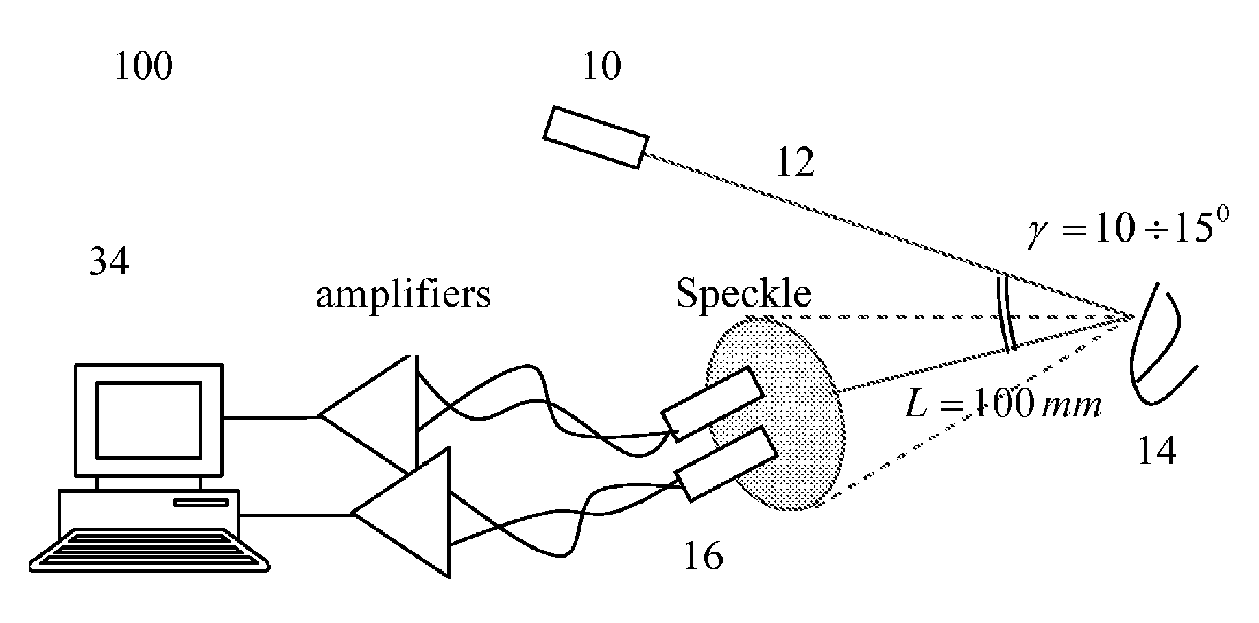
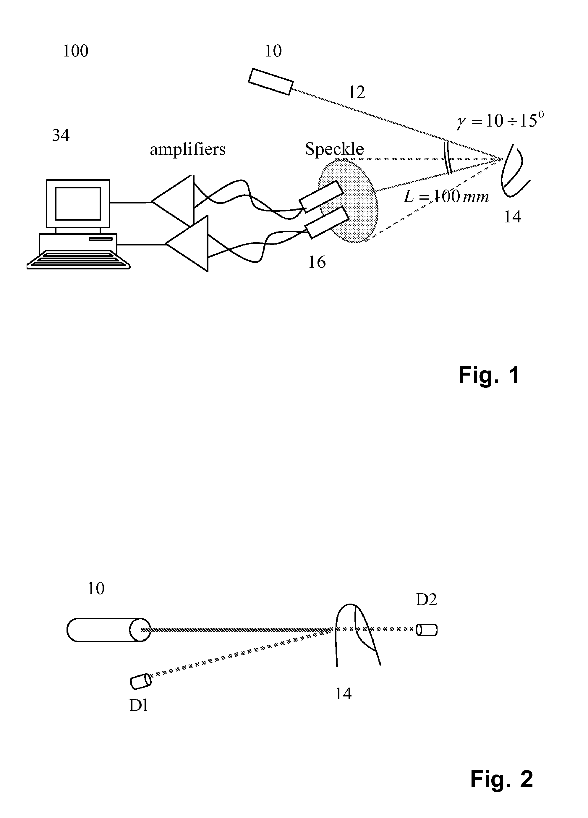
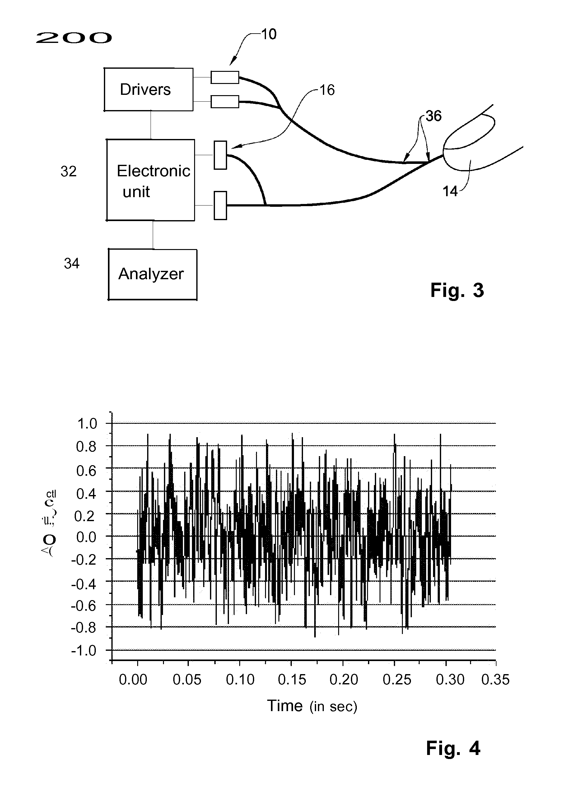
A system, method and medical tool are presented for use in non-invasive in vivo determination of at least one desired parameter or condition of a subject having a scattering medium in a target region. The measurement system comprises an illuminating system, a detection system, and a control system. The illumination system comprises at least one light source configured for generating partially or entirely coherent light to be applied to the target region to cause a light response signal from the illuminated region. The detection system comprises at least one light detection unit configured for detecting time-dependent fluctuations of the intensity of the light response and generating data indicative of a dynamic light scattering (DLS) measurement. The control system is configured and operable to receive and analyze the data indicative of the DLS measurement to determine the at least one desired parameter or condition, and generate output data indicative thereof.

Description

CROSS-REFERENCE TO RELATED APPLICATIONS[0001]This application is a continuation of U.S. Non-Provisional application Ser. No. 12 / 431,469 filed on Apr. 28, 2009, which is a continuation of International Application No. PCT / IL2007 / 001317, filed on Oct. 30, 2007, which in turn claims the benefit under 35 USC 119(e) of U.S. Provisional Application No. 60 / 855,143, filed on Oct. 30, 2006. Each of the aforementioned patent applications including U.S. Non-Provisional application Ser. No. 12 / 431,469, International Application No. PCT / IL2007 / 001317, and U.S. Provisional Application No. 60 / 855,143 is incorporated herein by reference in its entirety.FIELD OF THE INVENTION[0002]The present invention relates to a system and method for in vivo measurement of biological parameters of a subject.BACKGROUND OF THE INVENTION[0003]Near infrared spectroscopy (NIRS) is a well-established non-invasive technique which allows for the determination of tissue and blood analytes conditions based on spectro-photo...

Claims


Application Information

Patent Timeline
Patent Type & Authority Applications(United States)
IPC IPC(8): A61B5/0205A61B5/145A61B5/1455
CPCA61B5/0205A61B5/14532A61B5/14552A61B5/024A61B5/0265A61B5/14551A61B5/7246A61B5/7278
Inventor FINE, ILYA
Owner ELFI TECH
Learn More