Internal combustion engine which can be operated with liquid and with gaseous fuel and a method for operating an internal combustion engine of this kind

a technology of internal combustion engine and gaseous fuel, which is applied in the direction of combustion engine, machine/engine, output power, etc., can solve the problems of high pumping loss, relatively little time available for fuel injection, and particularly disadvantageous load control methods, so as to achieve greater efficiency, lower compression ratio, and higher compression ratio

Active Publication Date: 2014-04-17
FORD GLOBAL TECH LLC
View PDF24 Cites 4 Cited by
  • Summary
  • Abstract
  • Description
  • Claims
  • Application Information

AI Technical Summary

Benefits of technology

[0020]The present disclosure describes a system for an engine comprising a direct injection nozzle for injecting gaseous fuel into a cylinder of an engine in a second operating mode; an intake injection nozzle for injecting liquid fuel into an intake port of the engine in a first operating mode; and a valve gear suitable to adjust timing of opening and closing of an inlet valve. Preferential injection of a gaseous fuel such as compressed natural gas directly into the cylinder increases efficiency and allows for reduced heat exposure to the lesser used liquid gas injectors mounted in the intake port, reducing coking of these injectors.

Problems solved by technology

This method of load control proves particularly disadvantageous in the part-load range since low loads require severe throttling and a large pressure reduction in the induced air.
This results in high pumping losses.
The disadvantage with direct injection is that there is relatively little time available for injection of the fuel, mixture preparation in the combustion chamber, namely preparation of the fuel, possibly by vaporization, mixing of the charge air and the fuel and ignition of the prepared mixture.
A relatively high compression ratio which allows problem-free operation of the internal combustion engine with the gaseous fuel can then lead to knocking in the case of operation with liquid fuel.
In the case of internal combustion engines pressure-charged by means of exhaust gas turbocharging, in particular, this has the disadvantageous effect that the turbocharger may perform additional volumetric work in order to recompress the gas that has expanded in the intake system.
Without continuous use of the injection nozzle for the purpose of fuel injection, the lack of the cooling which is generally brought about by the fuel introduced may lead to high temperatures in areas of the injection nozzle which face or are adjacent to the combustion chamber.
The high temperatures can lead to thermal overloading of the nozzle and also to coking, with even very small quantities of fuel left behind on the injection device during injection burning incompletely if there is a deficiency of oxygen.
On the one hand, these coking residues can modify the geometry of the injection device in a disadvantageous way and affect or hinder the formation of the injection jet, thereby noticeably disrupting mixture preparation.
On the other hand, fuel injected in the first operating mode is deposited in the porous coking residues and then often burns incompletely if there is a deficiency of oxygen, forming soot which, in turn, contributes to an increase in particulate emissions.
Moreover, coking residues may break away, owing, for example, to mechanical stress due to a pressure wave propagating in the combustion chamber or the action of the injection jet.
The residues broken away in this way can lead to damage in the exhaust system and can, for example, impair the ability to function of exhaust gas aftertreatment systems provided in the exhaust system.
Owing to the high temperatures, coke deposits may also form within the nozzle, and these can not only affect or hinder the formation of the injection jet and disrupt mixture preparation but, what is more, can jeopardize the ability to function of the nozzle overall.
This is not conducive to operation of the internal combustion engine in the second, gaseous fuel operating mode as frequently and for as long as possible.

Method used


Image

  • Internal combustion engine which can be operated with liquid and with gaseous fuel and a method for operating an internal combustion engine of this kind
  • Internal combustion engine which can be operated with liquid and with gaseous fuel and a method for operating an internal combustion engine of this kind
  • Internal combustion engine which can be operated with liquid and with gaseous fuel and a method for operating an internal combustion engine of this kind

Examples


Embodiment Construction

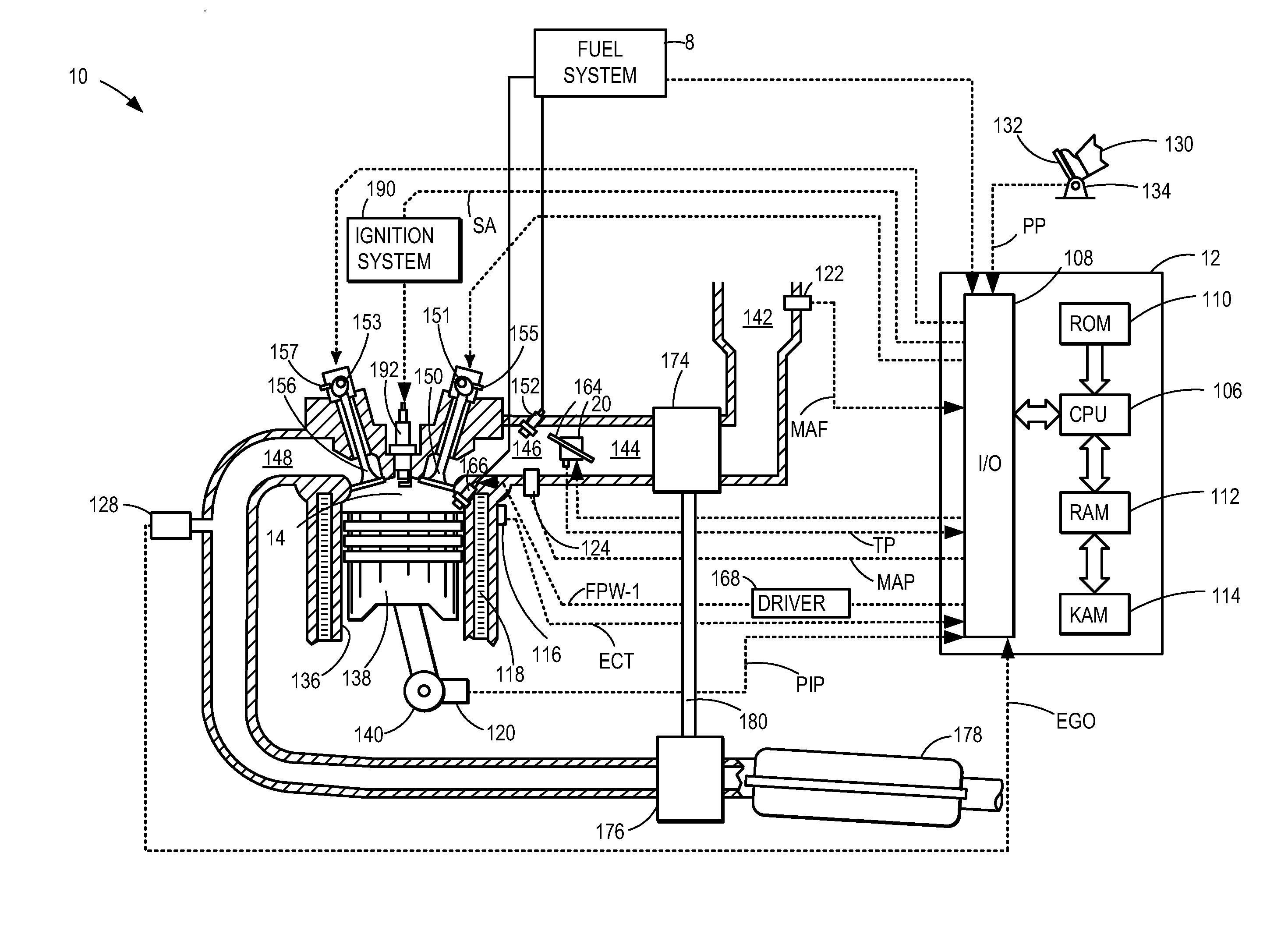
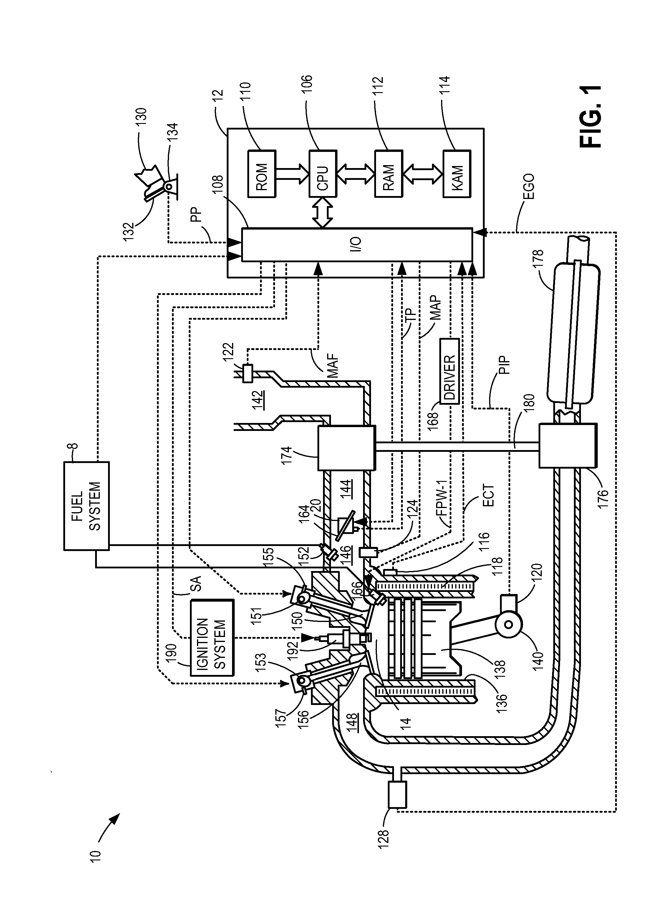
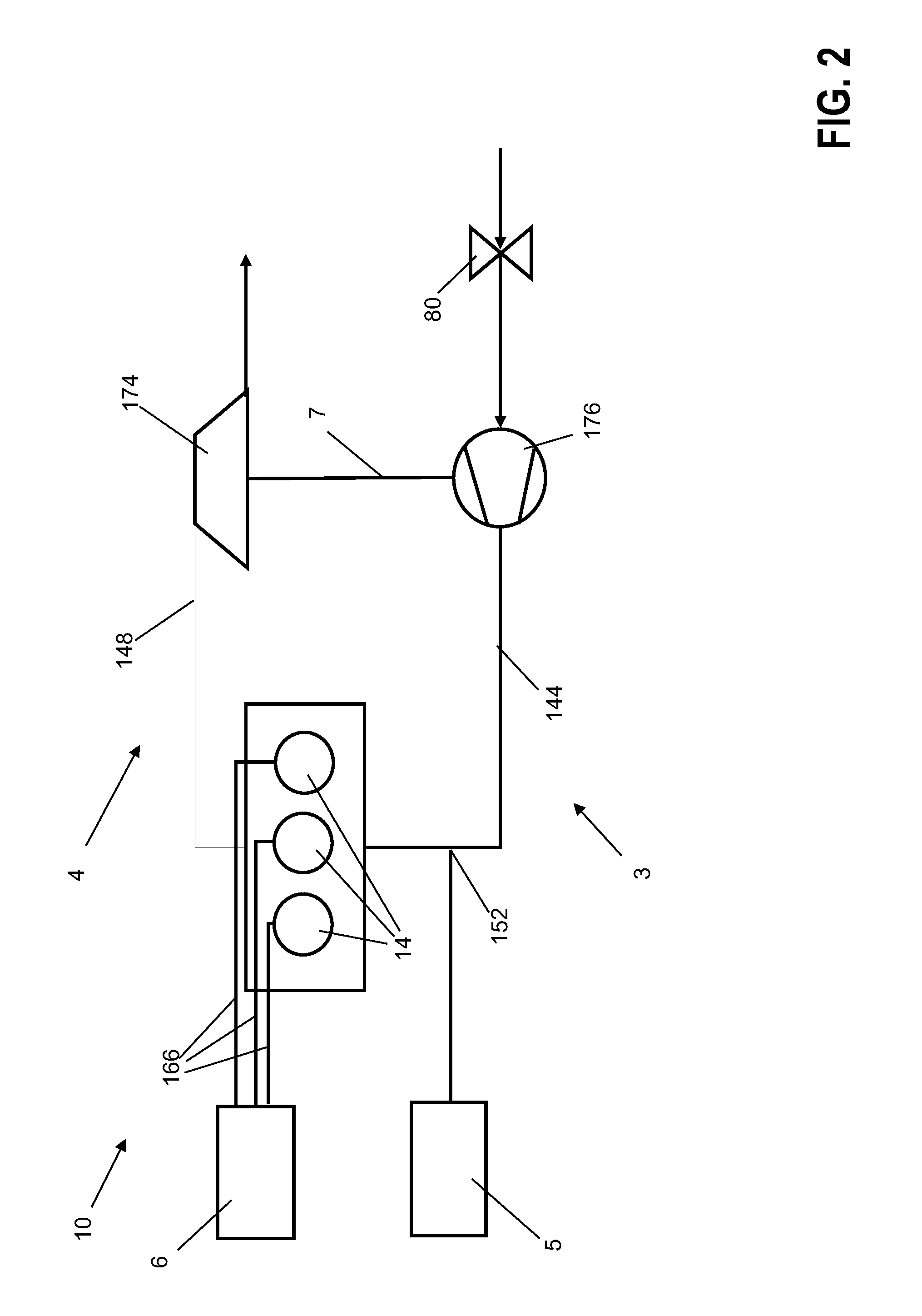
[0027]The disclosure is described in greater detailed below in reference to the drawings. An example cylinder in accordance with the present disclosure is shown in FIG. 1 with an overview of the separate fuel tanks and injection systems shown in FIG. 2. FIG. 3 details a method by which an operating mode for the engine described in FIGS. 1 and 2 may be selected. FIG. 4 shows a method of operating an engine in a first and second operating mode once a mode has been determined.

[0028]FIG. 1 depicts an example embodiment of a combustion chamber or cylinder of internal combustion engine 10. Engine 10 may receive control parameters from a control system including controller 12 and input from a vehicle operator 130 via an input device 132. In this example, input device 132 includes an accelerator pedal and a pedal position sensor 134 for generating a proportional pedal position signal PP. Cylinder (herein also “combustion chamber’) 14 of engine 10 may include combustion chamber walls 136 wit...


PUM


Abstract

The application describes a system for an engine comprising a direct injection nozzle for injecting gaseous fuel into a cylinder of an engine in a second operating mode; an intake injection nozzle for injecting liquid fuel into an intake port of the engine in a first operating mode; and a valve gear suitable to adjust timing of opening and closing of an inlet valve. Preferential injection of a gaseous fuel such as compressed natural gas directly into the cylinder increases efficiency and allows for reduced heat exposure to the lesser used liquid gas injectors mounted in the intake port, reducing coking of these injectors.

Description

CROSS REFERENCE TO RELATED APPLICATIONS[0001]The present application claims priority to German Patent Application 102012218789.8, filed on Oct. 16, 2012, the entire contents of which are hereby incorporated by reference for all purposes.TECHNICAL FIELD[0002]The disclosure relates to an internal combustion engine which can be operated with liquid fuel in a first operating mode and with gaseous fuel in a second operating mode.BACKGROUND AND SUMMARY[0003]With increasingly stringent emissions and efficiency regulations there is an increasing push toward the use of alternative fuels in internal combustion engines. In the context of the present disclosure, the term “internal combustion engine” comprises applied-ignition Otto engines especially. In the case of Otto engines, for example, not only gasoline as the traditional Otto engine fuel but also, for example, liquefied gas (LPG—Liquefied Petroleum Gas), a propane / butane mixture, which is also referred to as autogas, or natural gas (CNG—...

Claims


Application Information

Patent Timeline
Patent Type & Authority Applications(United States)
IPC IPC(8): F02B17/00
CPCF02B17/005F02D13/0203F02D15/00F02D19/0644F02D19/0647F02D19/0689Y02T10/12Y02T10/30
Inventor WEBER, CARSTENKRAMER, ULRICHWIRTH, MARTIN
Owner FORD GLOBAL TECH LLC
Why Eureka
Try Eureka