Gate driving circuit

a driving circuit and gate technology, applied in the direction of digital storage, pulse technique, instruments, etc., can solve the problems of gate driving circuit b>100/b> not working properly, current leakage of energy-store unit, etc., and achieve the effect of preventing current leakage of shift registers

Active Publication Date: 2014-04-17
AU OPTRONICS CORP
View PDF13 Cites 86 Cited by
  • Summary
  • Abstract
  • Description
  • Claims
  • Application Information

AI Technical Summary

Benefits of technology

[0008]The present invention further provides a method for preventing current leakage of a shift register. The method comprises providing a shift register comprising an energy-store unit for performing a charging process according to a previous-stage gate signal in order to provide a driving voltage, and a transistor having a first terminal electrically connected to the energy-store unit for pulling down the driving voltage of the energy-store unit to a low voltage level when being turned on; and when a gate signal outputted by the shift register is pulled up to a high voltage level according to the driving voltage, controlling a voltage level of the second terminal of the transistor, such that the voltage level of the second terminal of the transistor is higher than a voltage level of a control terminal of the transistor.

Problems solved by technology

However, in operation of the shift register 110, 120, 130, improper circuit design of the shift register 110, 120, 130 may cause the energy-store unit current leakage, such that the gate signal G(n−1), G(n), G(N+1) may not be able to be pulled up to a target voltage level smoothly, thus the gate driving circuit 100 can not work properly.

Method used


Image

  • Gate driving circuit
  • Gate driving circuit
  • Gate driving circuit

Examples


Embodiment Construction

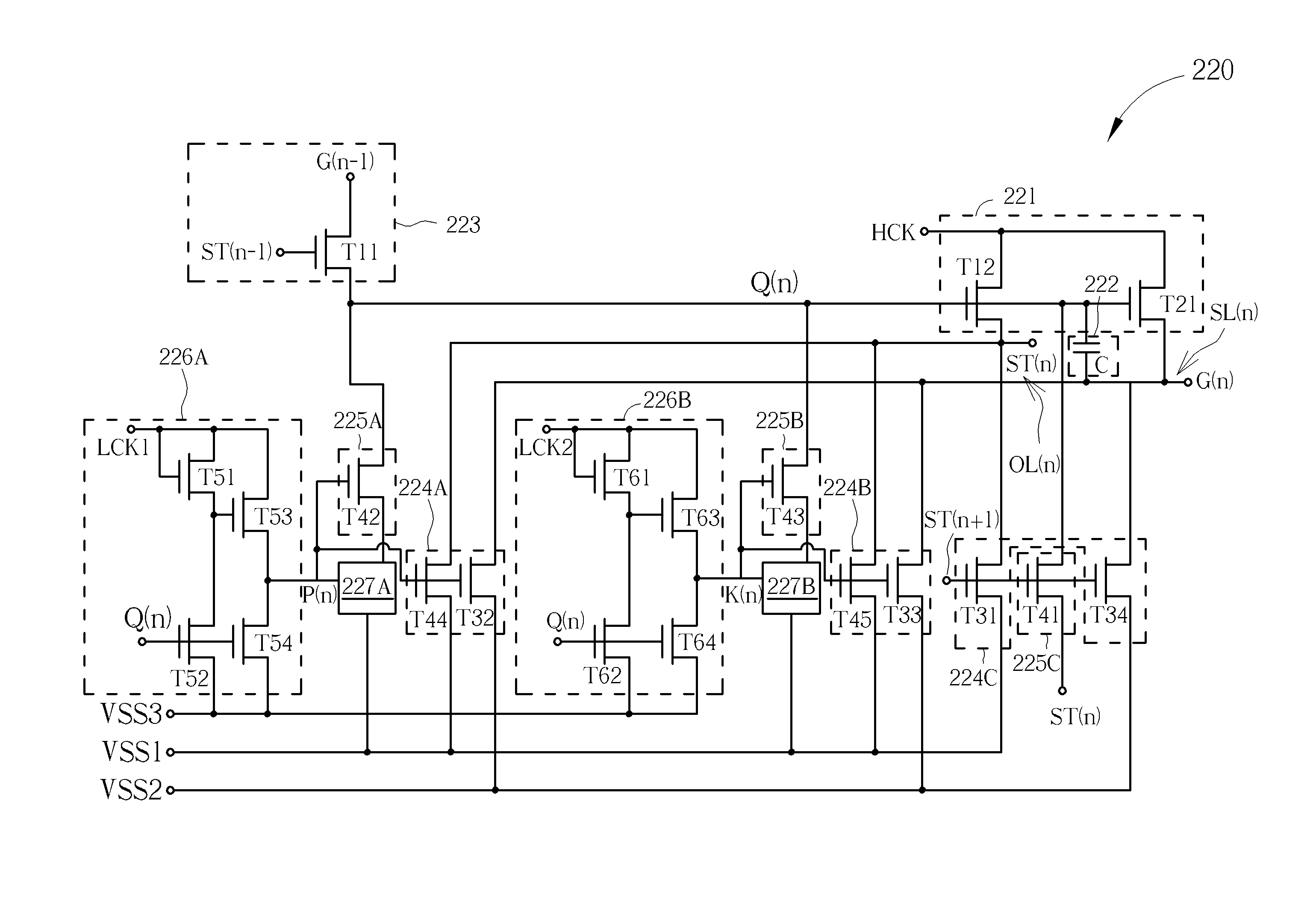
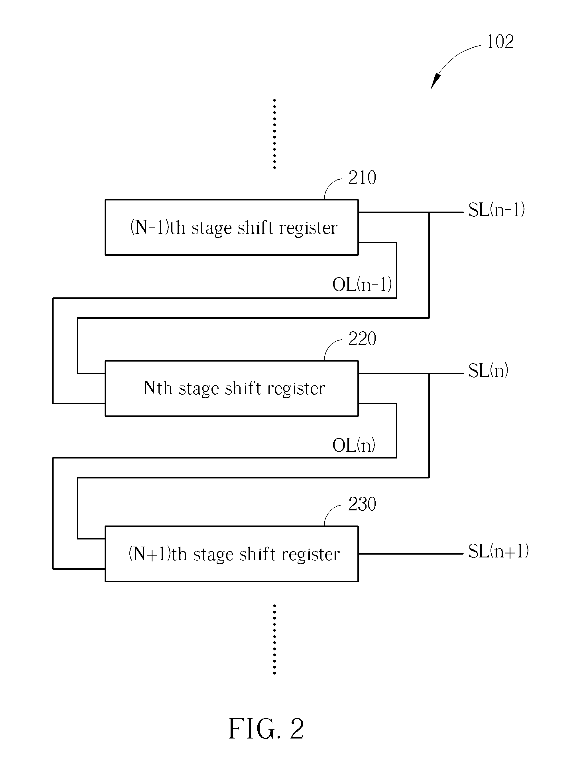
[0017]Please refer to FIG. 2 to FIG. 5. FIG. 2 is a diagram showing a gate driving circuit 200 of the present invention. FIG. 3 is a diagram showing an Nth stage shift register 220 of the gate driving circuit 200 in FIG. 2. FIG. 4 is a diagram showing a first leakage-preventing unit 227A of the Nth stage shift register 220 in FIG. 3. FIG. 5 is a diagram showing a second leakage-preventing unit 227B of the Nth stage shift register 220 in FIG. 3. As shown in figures, the gate driving circuit 200 comprises plural-stage shift registers. For ease of explanation, the gate driving circuit only illustrates an (N−1)th stage shift register 210, an Nth stage shift register 220, and an (N+1)th stage shift register 230, wherein only an internal structure of the Nth stage shift register 220 is illustrated in the FIG. 3. The other shift registers are similar to the Nth stage shift register 220, thus, no further illustration is provided. The (N−1)th stage shift register 210 is for providing an outp...


PUM


Abstract

A shift register of a gate driving circuit includes a pull-up unit for pulling up a first output signal and a first gate signal to a high voltage level according to a driving voltage and a high-frequency clock signal, a start-up unit for transmitting a second gate signal, an energy-store unit for providing the driving voltage to the pull-up unit according to the second gate signal, a first discharging unit for pulling down the driving voltage to a first voltage level according to a first control signal, a first leakage-preventing unit for turning off the first discharging unit when the first gate signal reaches the high voltage level, a first pull-down unit for respectively pulling down the first output and first gate signals to the first and a second voltage levels according to the first control signal, and a first control unit for generating the first control signal.

Description

BACKGROUND OF THE INVENTION[0001]1. Field of the Invention[0002]The present invention relates to a gate driving circuit, and more particularly, to a gate driving circuit capable of reducing current leakage.[0003]2. Description of the Prior Art[0004]In general, a liquid crystal display device comprises a plurality of pixel units, a gate driving circuit, and a source driving circuit. The source driving circuit is for providing a plurality of data signals. The gate driving circuit comprises plural-stage shift registers for providing a plurality of gate driving signals in order to control the plurality of pixel units to be written with the plurality of data signals.[0005]Please refer to FIG. 1. FIG. 1 is a diagram showing a gate driving circuit 100 of the prior art. As shown in FIG. 1, the gate driving circuit 100 comprises plural-stage shift registers. For ease of explanation, the gate driving circuit only illustrates an (N−1)th stage shift register 110, an Nth stage shift register 120...

Claims


Application Information

Patent Timeline
Patent Type & Authority Applications(United States)
IPC IPC(8): H03K3/015
CPCH03K3/015G09G3/3677G09G2310/08G11C19/28G09G3/3655
Inventor CHANG, CHING-HUICHAN, PIN-YUHONG, KAI-WEICHEN, YUNG-CHIH
Owner AU OPTRONICS CORP
Why Eureka
Try Eureka