Device for thermally treating products with cleaning of the process liquid

a technology of process liquid and device, which is applied in the direction of package sterilisation, separation process, filtration separation, etc., can solve the problems of increasing machine height, affecting requiring considerable extra effort and cost, so as to achieve the separation performance of products, reduce the need for maintenance, and reduce the need for equipmen

Inactive Publication Date: 2014-04-24
KRONES AG
View PDF7 Cites 5 Cited by
  • Summary
  • Abstract
  • Description
  • Claims
  • Application Information

AI Technical Summary

Benefits of technology

[0027]So, a robust and inexpensive provision of a separation unit is permitted which involves relatively little maintenance requirements. The separation efficiency of this separation unit may provide clearly better separation performances than in screen-like units, such as a travelling screen or a plug-in screen. Moreover, the separation performance is practically not affected by the particle size. The lower risk of clogging of the machine thus reduces wear on nozzles, pumps or other installations of a device for the thermal treatment of products. It is also conceivable that devices or machines that use process water to be cleaned may be retrofitted with such a separation unit.

Problems solved by technology

A cross-zone travelling screen, as it is employed in many cases, has the disadvantage that the belt must be guided horizontally for this, and correspondingly, the essentially vertical water path results in an additional machine height.
This additional height may amount to, for example, up to 400 mm and involve considerable extra efforts and costs in the region of the conveyor means for supplying and discharging the containers.
In case of a separation in zones by one travelling screen each per zone, the costs incurred for separation are disproportionally high.
Both types of screen have the additional disadvantage that they may get clogged, for example due to suspended matter, slimy matter and substances swimming on the water.
This means that these screens may get choked.
There, these substances increasingly hinder the throughput through the screens.
In particular if plug-in screens are used, the plug-in screens must be possibly pulled out and cleaned, so that machines with plug-in screens involve a high amount of required work and / or personnel.
However, if one does not succeed, for example, in dissolving slimy matter or similar substances by chemical treatment, or if there are some troubles with the chemical water treatment, the screen surfaces of the mentioned screen types will get clogged all the faster.
Acicular broken glass may possibly still pass through such meshes which may then lead to a clogging of the nozzles for irrigation.
However, plastic nozzles may wear down from inside by broken glass or other solid substances of a diameter of less than 2-3 mm.
However, a regular exchange of the nozzles is not desired, and neither is uncontrolled splashing, for example by water escaping laterally from ragged or damaged nozzles.

Method used


Image

  • Device for thermally treating products with cleaning of the process liquid
  • Device for thermally treating products with cleaning of the process liquid
  • Device for thermally treating products with cleaning of the process liquid

Examples


Embodiment Construction

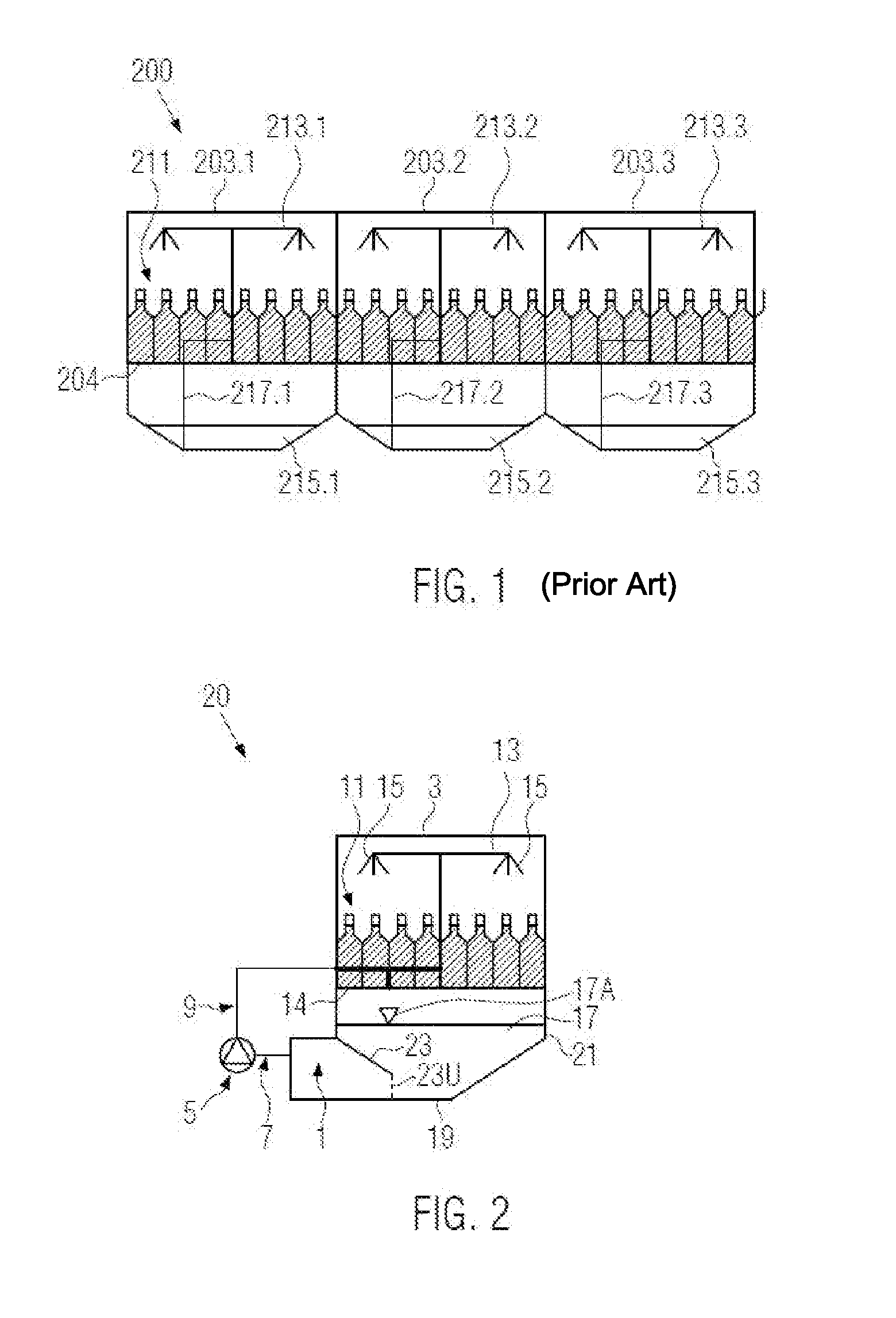
[0033]FIG. 1 shows, by way of example, a pasteurization device 200 with several treatment zones 203.1, 203.2, 203.3, as they are well-known in prior art. Containers, such as bottles with reference numeral 211, are transported through on a conveyor belt 204, for example from the left to the right in FIG. 1. Treatment zones 203.1, 203.2 and 203.3 may have different temperatures, i.e. the containers 211 are irrigated or sprayed from outside with process water of different temperatures. FIG. 1 shows irrigation devices 213.1, 213.2 and 213.3. In this example, the containers 211 are irrigated or sprayed from above. However, it is also possible to spray the containers 211 from the side. The process water used in each treatment zone runs downwards from the containers 211 and collects in the collecting tanks 215.1, 215.2 and 215.3. The process water may be pumped again to the irrigation devices 213.1, 213.2, 213.3 by pumps (not shown) via pipes 217.1, 217.2 and 217.3 and may be reused. Befor...


PUM

PropertyMeasurementUnit
angleaaaaaaaaaa
angleaaaaaaaaaa
heightaaaaaaaaaa

Abstract

A device for thermally treating products in containers, including supply and discharge conveyors for containers; with at least one irrigation or spraying zone for irrigating or spraying the containers with a process liquid, for example water; and a circulation circuit for at least partially reusing said process liquid, the circulation circuit including at least one pump; with at least one separation unit with several essentially parallel lamellae for cleaning the process liquid from particles, for example broken glass and/or sand, and the pump pumps the process liquid along the lamella.

Description

CROSS-REFERENCE TO RELATED APPLICATION[0001]The present application claims the benefit of priority of German Application No. 10 2012 219 184.4, filed Oct. 22, 2012. The entire text of the priority application is incorporated herein by reference in its entirety.FIELD OF THE DISCLOSURE[0002]The present disclosure relates to a device for thermally treating products with cleaning of the process liquid, such as used in bottling operations.BACKGROUND OF THE DISCLOSURE[0003]Devices for the thermal treatment of products in containers, for example bottles, PET containers and cans, are well-known in prior art. These devices may comprise, for example, pasteurization devices, heating or cooling devices. These devices often also occur in combination in a large, multi-zone pasteurization device to bring the products at least temporarily to different defined temperature levels. One example is the SHIELD pasteurization tunnel by Krones. Heat exchange is generally effected by irrigation with a proce...

Claims


Application Information

Patent Timeline
Patent Type & Authority Applications(United States)
IPC IPC(8): B01D35/02A61L2/04
CPCA23L3/04B65B55/02B01D21/0045B01D35/02B01D21/0042B01D21/2444A61L9/00A61L2/04A61L2/00
Inventor BRAUN, PAULMUNZER, JAN KARSTEN
Owner KRONES AG
Why Eureka
Try Eureka