System and method for diffusion combustion with oxidant-diluent mixing in a stoichiometric exhaust gas recirculation gas turbine system

a gas turbine and diffusion combustion technology, applied in the ignition of turbine/propulsion engine, combustion types, lighting and heating apparatus, etc., can solve the problems of affecting various exhaust emission and power requirements, consuming a large amount of gas turbine engines, and difficulty in controlling or maintaining premix flames, etc., to achieve low oxygen content and low oxygen content

Active Publication Date: 2014-05-08
GENERAL ELECTRIC CO +1
View PDF14 Cites 45 Cited by
  • Summary
  • Abstract
  • Description
  • Claims
  • Application Information

AI Technical Summary

Benefits of technology

[0007]In a third embodiment, a method includes introducing an oxidant to at least one oxidant compressor to produce a compressed oxidant stream, and introducing a recirculated low oxygen content gas stream to a compressor section of a gas turbine engine to produce a compressed low oxygen content gas stream. The method further includes mixing a first portion of the compressed low oxygen content gas stream with a first portion of the compressed oxidant stream and producing a diluted compressed oxidant stream. The method further includes introducing the diluted compressed oxidant stream and a fuel stream in a substantially stoichiometric ratio to at least one turbine combustor and mixing the diluted compressed oxidant stream and the fuel stream at the point of combustion and combusting the mixture of the diluted compressed oxidant stream and the fuel stream. The method further includes introducing a second portion of the compressed low oxygen content gas stream to the at least one turbine combustor and mixing it with the combusting streams of diluted compressed oxidant and fuel after the point of combustion and producing a high temperature high pressure low oxygen cont...

Problems solved by technology

Unfortunately, the premix flames may be difficult to control or maintain, which can impact various exhaust emission and power requirements.
Furthermore, gas turbine engines typically consume a ...

Method used


Image

  • System and method for diffusion combustion with oxidant-diluent mixing in a stoichiometric exhaust gas recirculation gas turbine system
  • System and method for diffusion combustion with oxidant-diluent mixing in a stoichiometric exhaust gas recirculation gas turbine system
  • System and method for diffusion combustion with oxidant-diluent mixing in a stoichiometric exhaust gas recirculation gas turbine system

Examples


embodiment 1

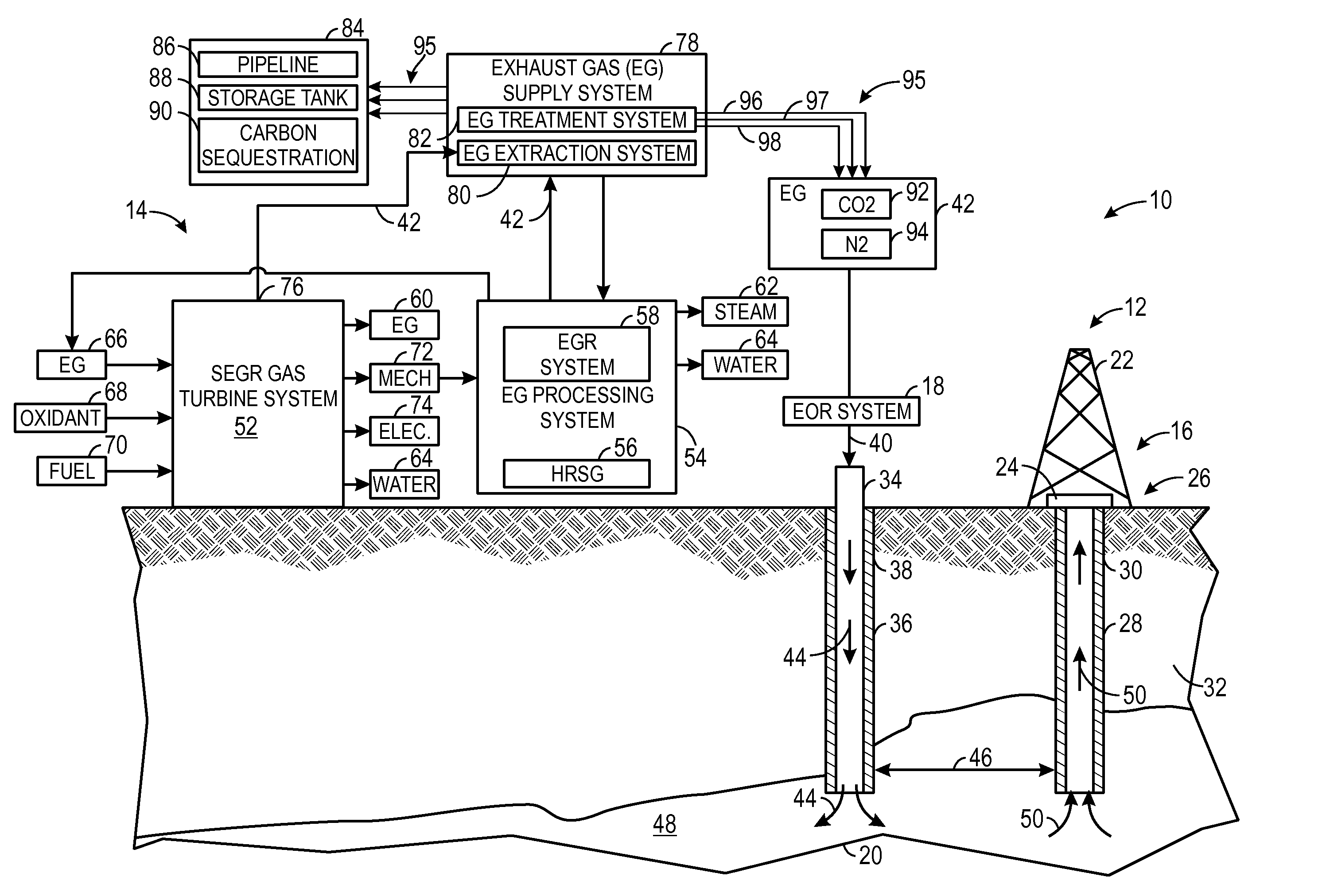
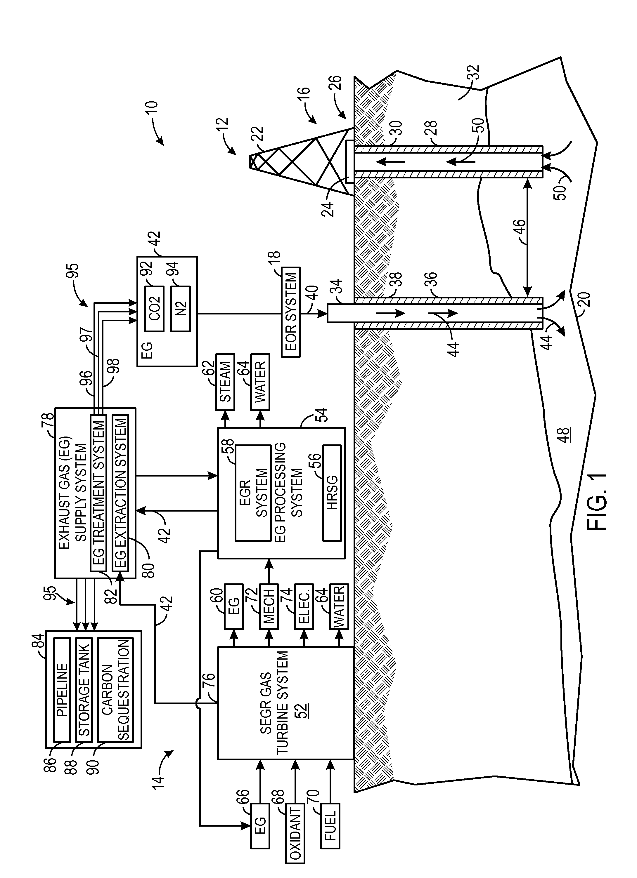
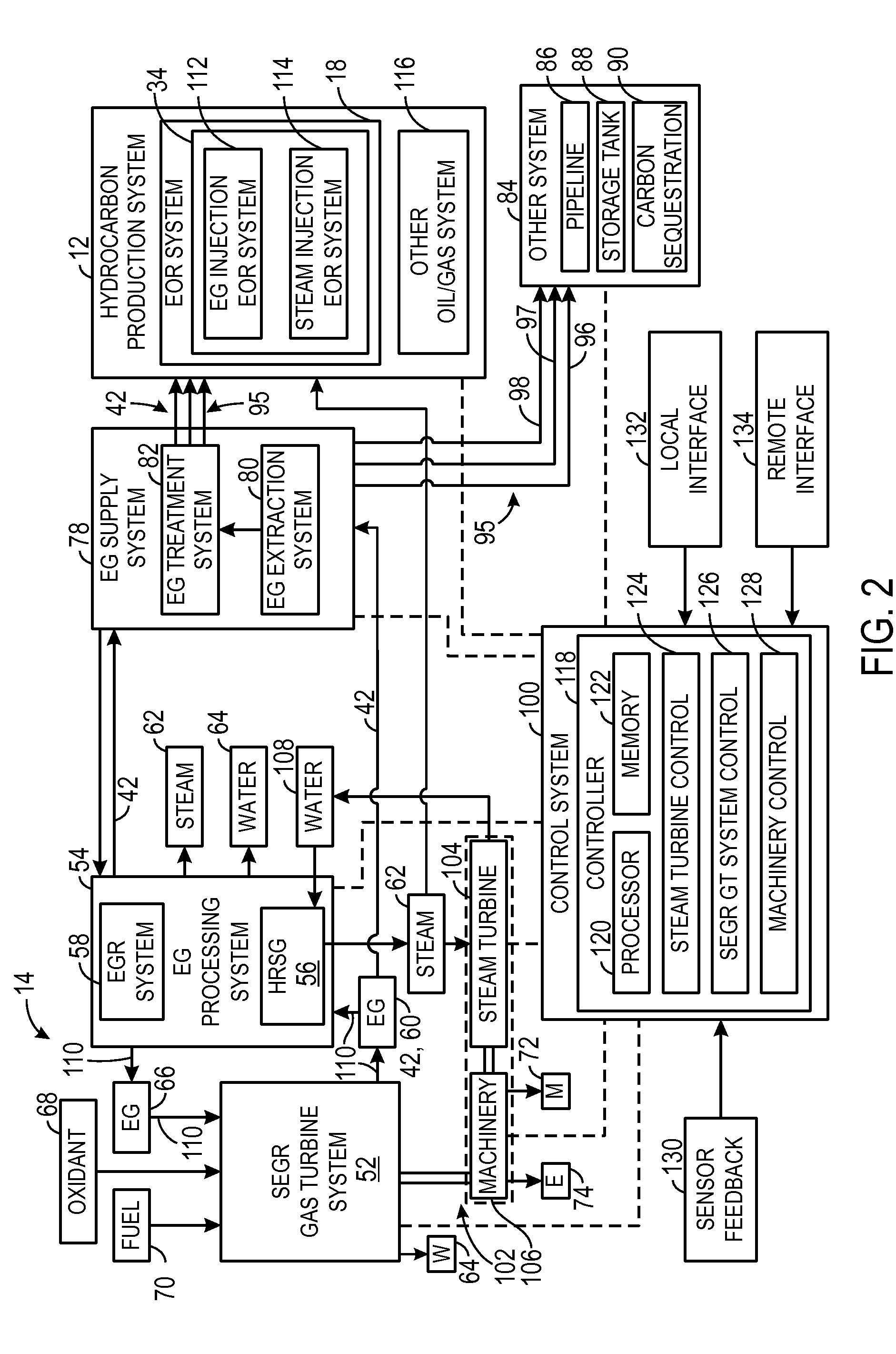
[0118]A system, comprising: a turbine combustor comprising a first diffusion fuel nozzle, wherein the first diffusion fuel nozzle comprises first and second passages that separately inject respective first and second flows into a chamber of the turbine combustor to produce a diffusion flame, wherein the first flow comprises a first fuel, and the second flow comprises a first oxidant and a first diluent; a turbine driven by combustion products from the diffusion flame in the turbine combustor; and an exhaust gas compressor, wherein the exhaust gas compressor is configured to compress and route an exhaust gas from the turbine to the turbine combustor along an exhaust recirculation path.

embodiment 2

[0119]The system of embodiment 1, wherein the first diluent comprises a portion of the exhaust gas, steam, nitrogen, another inert gas, or any combination thereof.

embodiment 3

[0120]The system of any preceding embodiment, wherein the first diluent comprises a portion of the exhaust gas.


PUM


Abstract

A system is provided with a turbine combustor having a first diffusion fuel nozzle, wherein the first diffusion fuel nozzle has first and second passages that separately inject respective first and second flows into a chamber of the turbine combustor to produce a diffusion flame. The first flow includes a first fuel, and the second flow includes a first oxidant and a first diluent. The system includes a turbine driven by combustion products from the diffusion flame in the turbine combustor. The system also includes an exhaust gas compressor, wherein the exhaust gas compressor is configured to compress and route an exhaust gas from the turbine to the turbine combustor along an exhaust recirculation path.

Description

CROSS-REFERENCE TO RELATED APPLICATIONS[0001]This application claims priority to and benefit of U.S. Provisional Patent Application No. 61 / 722,118, entitled “SYSTEM AND METHOD FOR DIFFUSION COMBUSTION IN A STOICHIOMETRIC EXHAUST GAS RECIRCULATION GAS TURBINE SYSTEM,” filed on Nov. 2, 2012, U.S. Provisional Patent Application No. 61 / 722,115, entitled “SYSTEM AND METHOD FOR DIFFUSION COMBUSTION WITH FUEL-DILUENT MIXING IN A STOICHIOMETRIC EXHAUST GAS RECIRCULATION GAS TURBINE SYSTEM,” filed on Nov. 2, 2012, U.S. Provisional Patent Application No. 61 / 722,114, entitled “SYSTEM AND METHOD FOR DIFFUSION COMBUSTION WITH OXIDANT-DILUENT MIXING IN A STOICHIOMETRIC EXHAUST GAS RECIRCULATION GAS TURBINE SYSTEM,” filed on Nov. 2, 2012, and U.S. Provisional Patent Application No. 61 / 722,111, entitled “SYSTEM AND METHOD FOR LOAD CONTROL WITH DIFFUSION COMBUSTION IN A STOICHIOMETRIC EXHAUST GAS RECIRCULATION GAS TURBINE SYSTEM,” filed on Nov. 2, 2012, all of which are herein incorporated by refere...

Claims


Application Information

Patent Timeline
IPC IPC(8): F02C7/22
CPCF02C7/22F05D2270/08F02C3/34F23K5/007F23L7/00F23L7/005F23C9/00F23R3/40F05D2260/61F23C2202/20F23C2202/30Y02E20/16F23R3/28Y02T50/60F23D14/20F02C1/005F23D14/22F02C3/30F02C1/08F23C9/08F23D14/58F23R3/343F23L2900/07002
Inventor HUNTINGTON, RICHARD A.DHANUKA, SULABH K.SLOBODYANSKIY, ILYA ALEKSANDROVICH
Owner GENERAL ELECTRIC CO
Why Eureka
Try Eureka