Construction element for co2 capture

a construction element and co2 capture technology, applied in the field of building elements, can solve the problems of corrosion or degradation of equipment materials, further and potentially more dramatic changes in climate, etc., and achieve the effect of simple and less expensive materials and positive effect on li

Active Publication Date: 2014-05-08
AKER CARBON CAPTURE NORWAY AS
View PDF2 Cites 13 Cited by
  • Summary
  • Abstract
  • Description
  • Claims
  • Application Information

AI Technical Summary

Benefits of technology

[0024]According to one embodiment, synthetic hydrotalcite is added to polymer mixture. Hydrotalcite is assumed to have a positive effect on the lifetime of a polyolefin in amine solutions at the operating temperatures of a CO2 capture plant. Further testing is performed to confirm the assumption.
[0025]According to one embodiment, the surface of the building element expected to being exposed to the aqueous amine absorbent, amine vapour and / or steam is coated with said polyolefin composition. Alternatively, the surface of the building element expected to being exposed to aqueous amine solution, vapour thereof or steam is a liner comprising said polyolefin composition which is fixed to the surface of the construction element. The coating or the liner will according to these embodiments, protect the underlying structures from exposure to amine solutions. Aqueous amine solutions are extremely corrosive and by protecting the underlying structure with a polymer coating or a polymer liner according to the present invention, materials that are not resistant to corrosion by the amine solution are protected from exposure, making it possible to use simpler and less expensive materials for building of the plant.
[0026]Examples on construction elements according to the present invention are an absorption column, a desorption column, a tube, a liner, a tray, or a column packing element. All of said elements are exposed to hot amine solutions and a coating or liner comprising the present polyolefin mixture may be beneficial.

Problems solved by technology

According to simulation models, it is suspected to cause further and potentially more dramatic changes in the climate in the future.
For instance the amines may cause corrosion or degradation of the equipment material, particularly the columns, its inserts and piping where the amines are present in significant amounts and at relatively high temperatures.

Method used


Image

  • Construction element for co2 capture
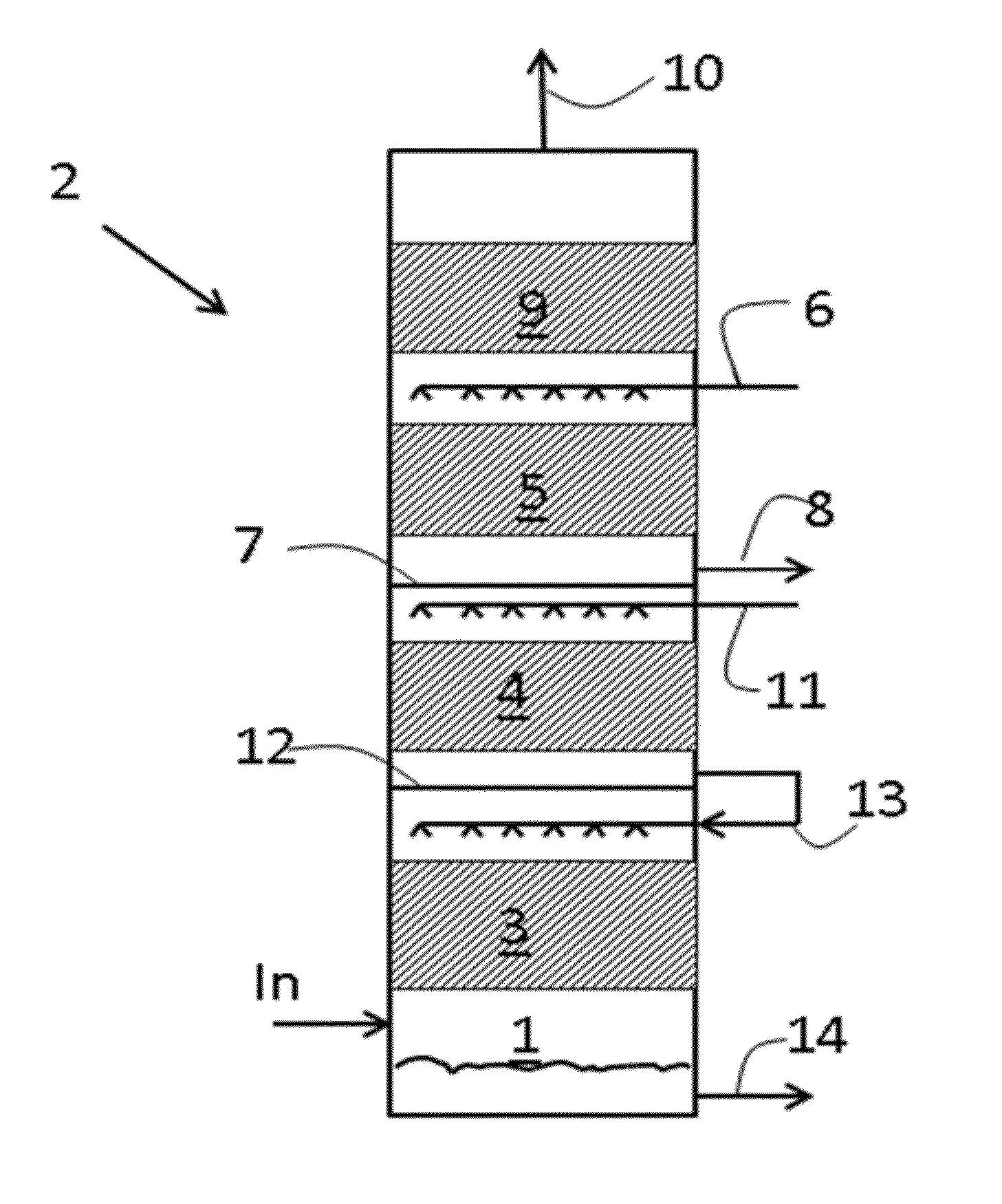
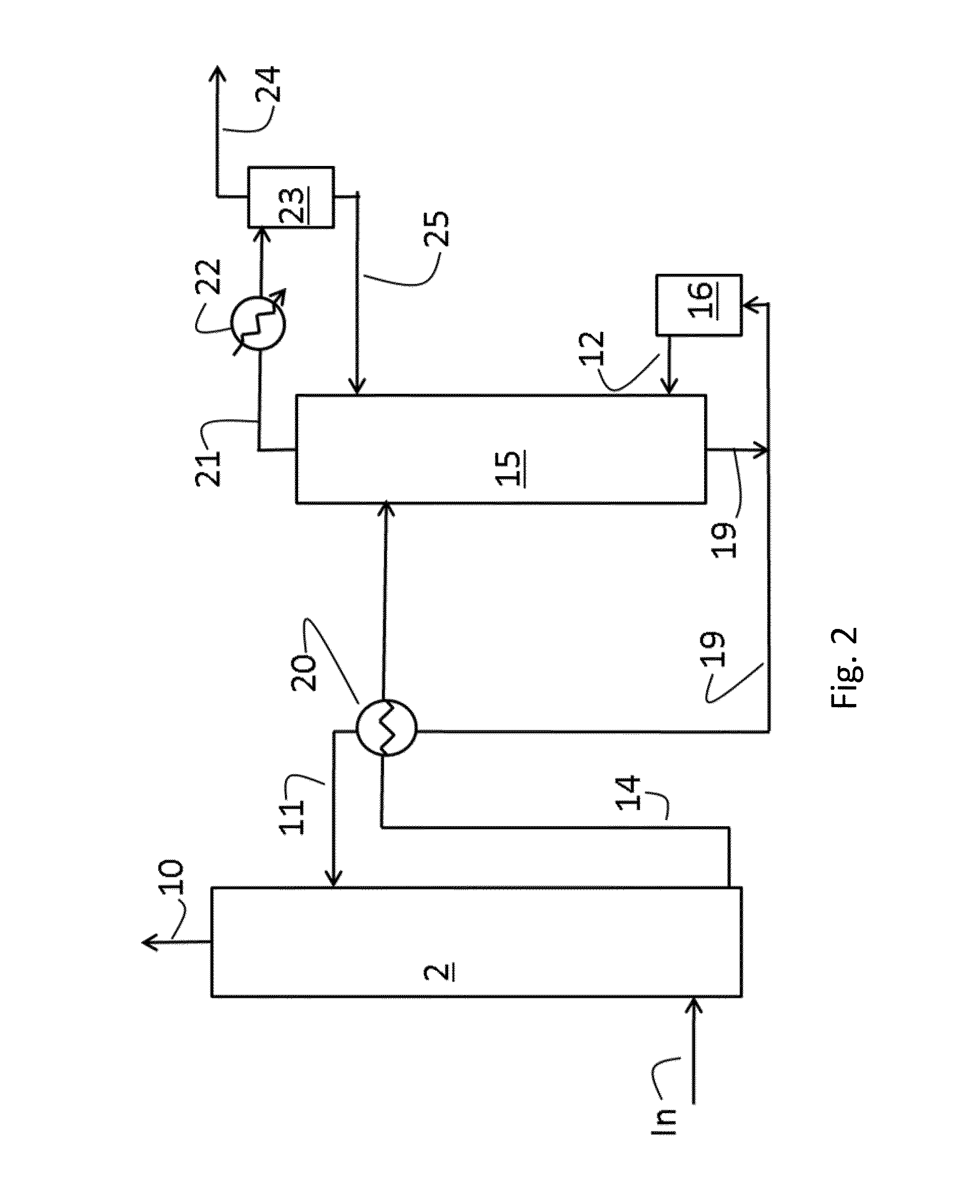
  • Construction element for co2 capture
  • Construction element for co2 capture

Examples


examples

[0245]The invention will now be described with reference to the following non-limiting examples.

Analytic Tests

[0246]Values quoted in the description and examples are measured according to the following tests:

[0247]The melt flow rate (MFR) is determined according to ISO 1133 and is indicated in g / 10 min. The MFR is an indication of the melt viscosity of the polymer. The MFR is determined at 230° C. for PP and at 190° C. PE. The load under which the melt flow rate is determined is usually indicated as a subscript, for instance MFR2 is measured under 2.16 kg load and MFR5 is measured under 5 kg load.

[0248]Density was measured according to ISO 1183.

[0249]The weight average molecular weight Mw and the molecular weight distribution (MWD=Mw / Mn wherein Mn is the number average molecular weight and Mw is the weight average molecular weight) is measured by a method based on ISO 16014-4:2003. A Waters 150CV plus instrument, equipped with refractive index detector and online viscosimeter was us...


PUM

PropertyMeasurementUnit
thicknessaaaaaaaaaa
temperaturesaaaaaaaaaa
mol %aaaaaaaaaa

Abstract

A construction element for a plant for capture of an acidic gas using an aqueous amine absorbent, wherein at least a part of a surface of said element comprises a polyolefin, and a hydrolytically stable antioxidant, is described. Additionally, a liner comprising said polyolefin and the hydrolytically stable antioxidant, is described. The construction element may be a column, a pipe, an insert, like a column packing element or a tray. An apparatus for capturing CO2 using the construction elements, is also described.

Description

TECHNICAL FIELD[0001]The present invention relates to a building element for capture of acidic gases, e.g. CO2, to a liner and inserts for use in the column and to an apparatus comprising the column, liner or inserts. The invention also concerns piping for use in methods of capturing acidic gases, e.g. CO2 as well as to methods of capturing acidic gases, e.g. CO2, using the afore-mentioned columns, liners and inserts.BACKGROUND ART[0002]The continually increasing combustion of fossil fuel, such as coal, natural gas, and oil, has resulted in a dramatic increase in the concentration of CO2 in the atmosphere. There is overwhelming evidence that the greenhouse effect is at least partly caused by this increased CO2 concentration and that this has already contributed to the climate changes that have occurred over the last decades. According to simulation models, it is suspected to cause further and potentially more dramatic changes in the climate in the future.[0003]As a result, scientist...

Claims


Application Information

Patent Timeline
Patent Type & Authority Applications(United States)
IPC IPC(8): B01D53/18B29C47/00B05D7/22B01D53/14
CPCB01D53/18B29C47/0004B05D7/222B01D53/1456B32B13/12B32B15/085F16L58/1009B01D53/1475B01D2252/204B01D2257/504B32B1/08B32B2597/00B29C48/022Y02C20/40Y02A50/20
Inventor JAMTVEDT, SVEINOYS.AE BUTTED.D, HARRYGJERP, JOHN OLEFORSBERG, FRANK HENNING
Owner AKER CARBON CAPTURE NORWAY AS
Why Eureka
Try Eureka