Dynamic fiber bragg grating interrogation system and method

a fiber bragg grating and interrogation system technology, applied in the direction of optical radiation measurement, instruments, using wave/particle radiation means, etc., can solve the problems of reducing the cost of the system, limiting the sampling frequency of the preventing the dynamic measurement from being impeded by sampling frequency limited optical spectrum analyzer components, etc., to achieve high frequency dynamic measurement.

Active Publication Date: 2014-05-15
UNIV HOUSTON SYST
View PDF1 Cites 10 Cited by
  • Summary
  • Abstract
  • Description
  • Claims
  • Application Information

AI Technical Summary

Benefits of technology

[0007]A fiber Bragg grating (FBG) interrogation system and method allows for high frequency dynamic measurement. The method may utilize a broad band light source connected to the sensing elements. Each sensing element may comprise two wavelength matching FBGs, a coupler, and a photodiode. The FBG closest to the light source may attenuate the central wavelength in the transmission spectrum and thus the reflection spectrum of the second FBG. Variations in intensity of the second FBG may be measured by the photodiode and can be calibrated to the desired measurands. The FBG interrogation system measures high frequency vibrations that are useful for structural health monitoring.

Problems solved by technology

While fiber Bragg gratings (FBGs) have been well studied and understood for quasi-static strain and temperature measurements, their use for high frequency, dynamic measurements were impeded by sampling frequency limited optical spectrum analyzer components.
A separate class of such methods exists in which regular FBGs can be used as the filter, thus potentially driving down costs and simplifying the system.
These wavelength-matched methods utilize dual FBGs per sensor to free the user from the cost and sampling frequency related limitations of specialized components, such as scanning optical filters, but may need additional equipment for multiplexing (e.g. switches).

Method used


Image

  • Dynamic fiber bragg grating interrogation system and method
  • Dynamic fiber bragg grating interrogation system and method
  • Dynamic fiber bragg grating interrogation system and method

Examples


experiment 1

[0046]FBG Sensor Directly Bonded to PZT Actuator

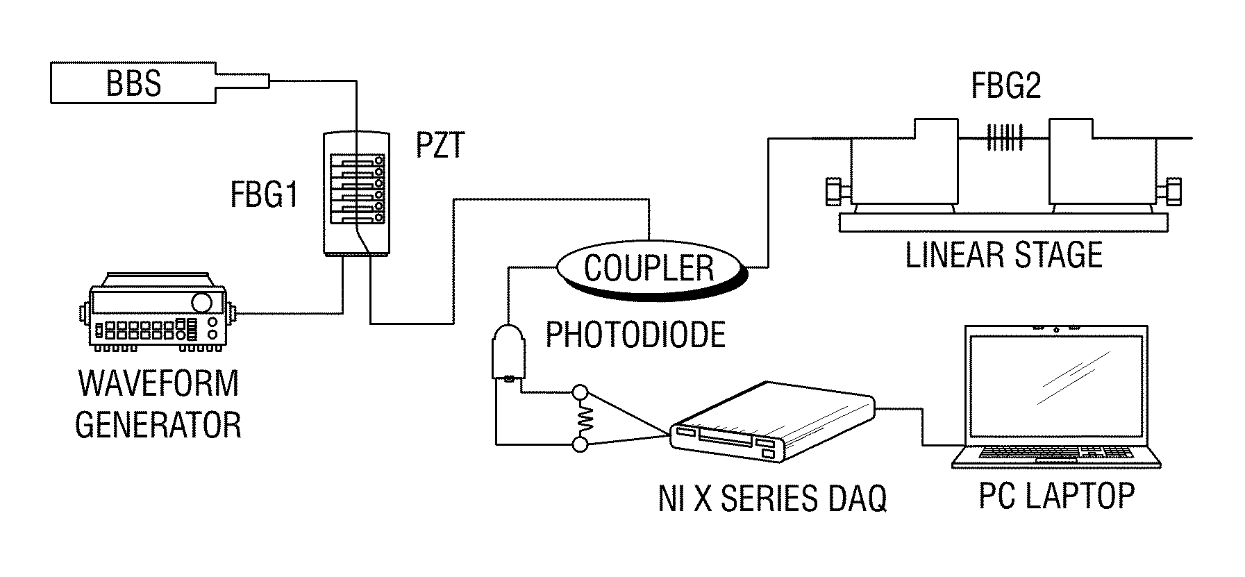
[0047]Two Type I FBGs with matching wavelengths at 1560 nm were used in the experimental setup as shown in FIG. 6. One of the FBGs (FBG1) was bonded via cyanoacrylate onto a 2.5″×1″ PZT wafer while the other (FBG2) was mounted on an adjustable linear stage. A waveform generator (Agilent 33120A) was used to drive the PZT wafer. The FBGs were illuminated using a broad band source (BBS) (ASE laser in the C band), and the power level at the overlapping wavelength was measured by a PIN photodiode (InGaAs, ETX 75HB). The voltage across a parallel resistor (51.1 kOhms) was recorded by an NI board (X series, PCIe / PXIe / USB-6361).

[0048]A sweep sine from 0 to 100 kHz over 4 seconds at 10 V was input into the PZT in order to examine the frequency response of the system. The sampling rate was set at 500 kHz.

experiment 2

[0049]FBG Sensor Bonded at a Distance Away from PZT Actuator

[0050]In the second experiment, an FBG strain sensor with a sensitivity of 2.2 pm / με was bonded via cyanoacrylate to a model wind turbine blade while another FBG with a matching wavelength at 1568 nm was mounted on a linear stage for precise wavelength adjustment (FIG. 7). In regards to FIG. 6, the setup of Experiment 2 is the same as Experiment 1 except that the PZT wafer is replaced with the wind turbine blade. Additionally, a 1 cm×1 cm piezoelectric patch was bonded using epoxy about 9 cm away from the FBG strain sensor.

[0051]A sweep sine from 0 to 100 kHz over 4 seconds at 10 V was input into the PZT in order to examine the frequency response of the system. The sampling rate was set at 500 kHz. In order to examine the impulse response of the turbine blade, an impulse was input at the middle of the wind turbine blade. To better capture transient responses, the impact test was sampled at 1 MHz for 12 seconds.

[0052]Using a...


PUM


Abstract

A fiber Bragg grating (FBG) interrogation method allows for high frequency dynamic measurement. The method may utilize a broad band light source connected to the sensing elements. Each sensing element may comprise two wavelength matching FBGs, a coupler, and a photodiode. The FBG closest to the light source may attenuate the central wavelength in the transmission spectrum and thus the reflection spectrum of the second FBG. Variations in intensity of the second FBG may be measured by the photodiode and can be calibrated to the desired measurands.

Description

RELATED APPLICATIONS[0001]This application claims the benefit of U.S. Provisional Patent Application No. 61 / 724,442 to Song et al., filed on Nov. 9, 2012, which is incorporated herein by reference.STATEMENT REGARDING SPONSORED RESEARCH[0002]Not Applicable.FIELD OF THE INVENTION[0003]This invention relates to dynamic fiber Bragg grating (FBG) interrogation systems and methods. More particularly, to systems and methods for high frequency interrogation of FBGs.BACKGROUND OF INVENTION[0004]In designing and handling mechanical structures, one commonly encounters situations in which the measurement of high frequency vibrations plays an important role. Such high frequency measurements are valuable especially in the area of structural health monitoring. While fiber Bragg gratings (FBGs) have been well studied and understood for quasi-static strain and temperature measurements, their use for high frequency, dynamic measurements were impeded by sampling frequency limited optical spectrum anal...

Claims


Application Information

Patent Timeline
Patent Type & Authority Applications(United States)
IPC IPC(8): G01H9/00
CPCG01H9/004G01D5/35316
Inventor SONG, GANGBINGHO, SIU CHUN MICHAELLIANG, RENLI, HONGNAN
Owner UNIV HOUSTON SYST
Why Eureka
Try Eureka