Optical device, projector, manufacturing method, and manufacturing support apparatus

Active Publication Date: 2014-05-15
CITIZEN WATCH CO LTD
View PDF4 Cites 2 Cited by
  • Summary
  • Abstract
  • Description
  • Claims
  • Application Information

AI Technical Summary

Benefits of technology

[0010]According to the present invention, an optical device that can shift the polarization direction of laser light at high speed can be provided. Adopting such an optical device offers an e

Problems solved by technology

The speckle patterns are created when beams of light emitted from different points of the projection optical system interfere with each other

Method used


Image

  • Optical device, projector, manufacturing method, and manufacturing support apparatus
  • Optical device, projector, manufacturing method, and manufacturing support apparatus
  • Optical device, projector, manufacturing method, and manufacturing support apparatus

Examples


embodiment

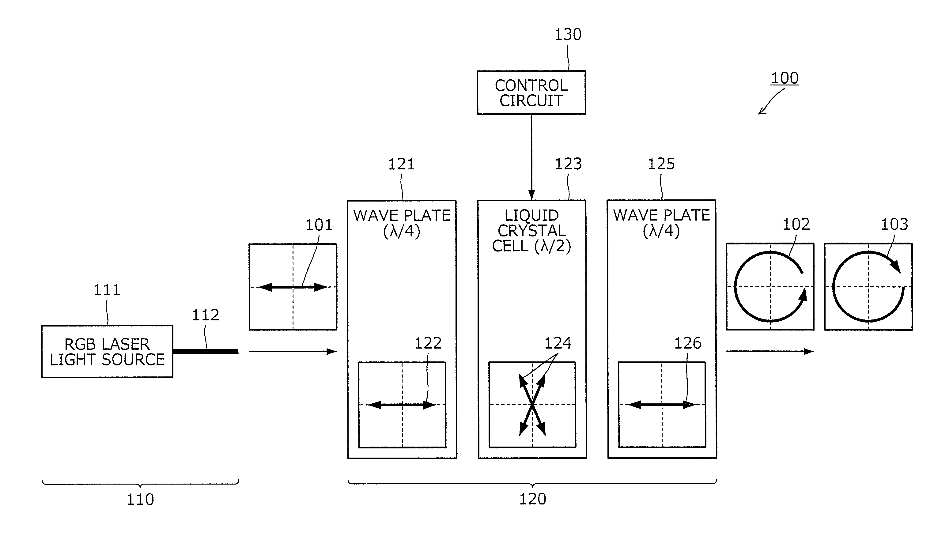
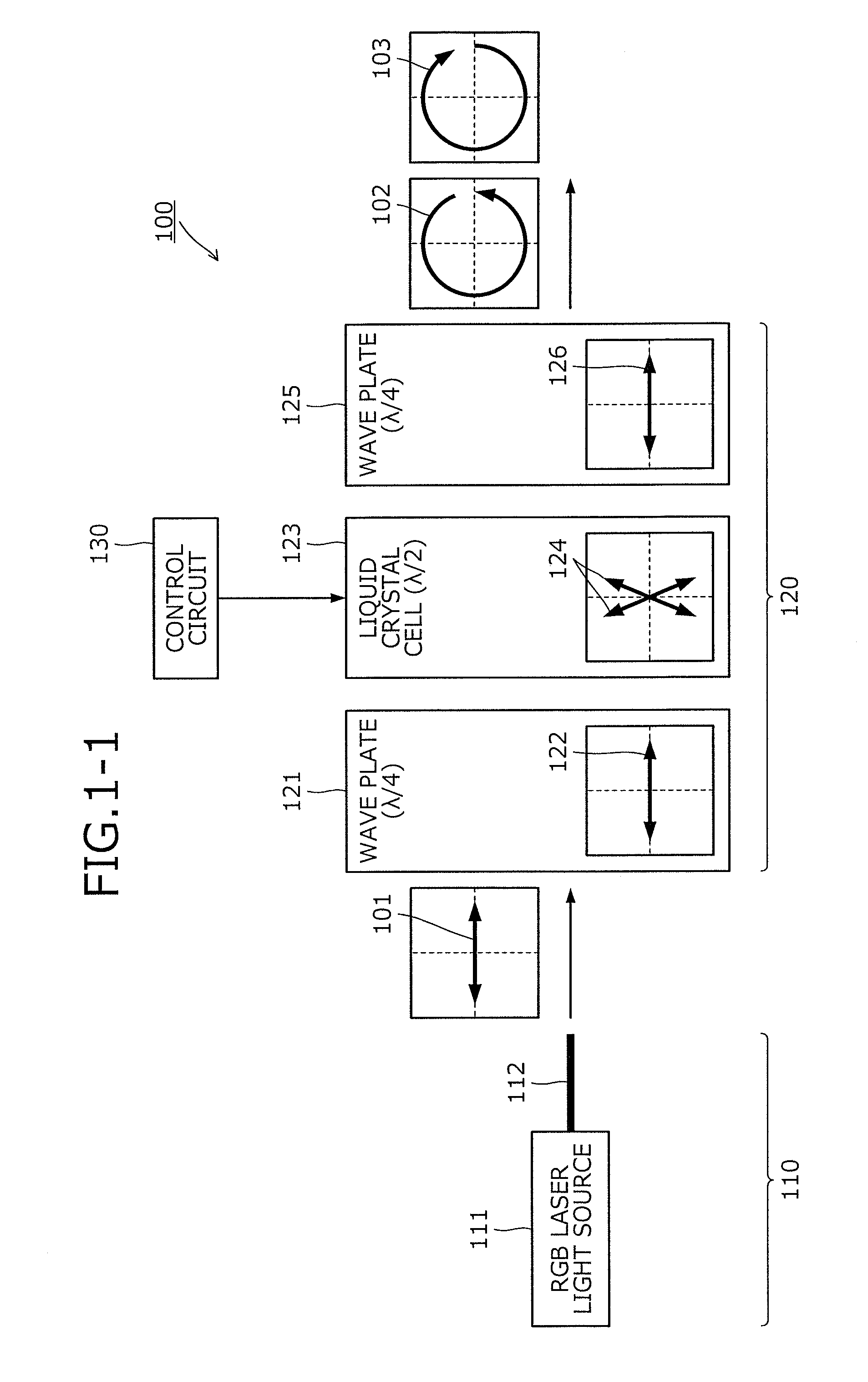
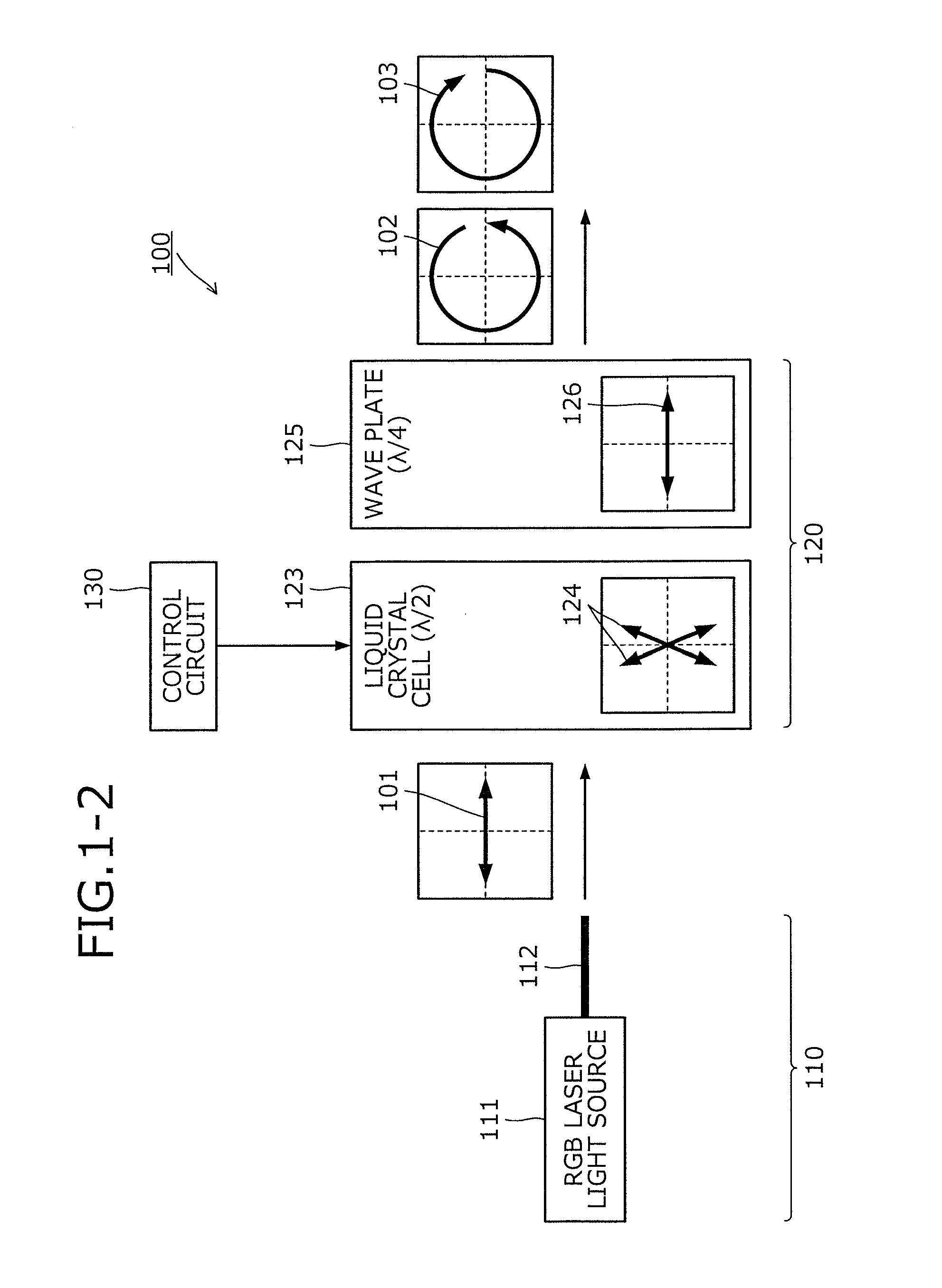
[0082]FIG. 1-1 depicts a configuration example of an optical device according to an embodiment. As depicted in FIG. 1-1, an optical device 100 includes a light source unit 110, a liquid crystal device 120, and a control circuit 130. The light source unit 110 and the control circuit 130 may be disposed outside the optical device 100.

[0083]The light source unit 110 emits laser light of a given wavelength in a given polarization state. Laser light is, for example, linearly polarized laser light that includes multiple beams of primary color light in terms of space or time. The light source unit 110, for example, includes an RGB laser light source 111 and a polarization-maintaining fiber 112. The RGB laser light source 111 emits linearly polarized laser light that includes multiple beams of primary color (red, green, and blue) light. The light source unit 110 is, for example, a light source unit that operates by the field sequential method to cause light sources for respective colors to ...


PUM


Abstract

A light source unit (110) emits linearly polarized laser light of a given wavelength. A wave plate (121) transmits the laser light emitted from the light source unit (110) and has a phase delay axis of which the direction is adjusted to about 0 degrees with respect to the polarization direction (101) of the laser light. A liquid crystal cell (123) transmits laser light that has passed through the wave plate (121) and by a switchable rotation amount, rotates the polarization direction (101) of the laser light transmitted through the liquid crystal cell (123). A wave plate (125) transmits laser light that has passed through the liquid crystal cell (123); and further has a phase delay axis of which the direction is adjusted to about 0 degrees with respect to the polarization direction (101) of the laser light.

Description

TECHNICAL FIELD[0001]The present invention relates to an optical device that generates laser light, to a projector, to a manufacturing method, and to a manufacturing support apparatus.BACKGROUND ART[0002]A conventional projector is known, which modulates light emitted from a lighting device by a spatial light modulator and projects onto a screen, an enlarged form of modulated image light through a projection optical system, such as projection lens. Conventionally, a metal hydride lamp, halogen lamp, etc. has been used as the lighting device of the projector. In recent years, however, use of a laser diode (LD) has been proposed in order to reduce the size of the lighting device and the projector.[0003]However, because laser light is coherent light, video light projected in an enlarged form develops speckle patterns having randomly distributed luminous dots and dark dots. The speckle patterns are created when beams of light emitted from different points of the projection optical syste...

Claims


Application Information

Patent Timeline
IPC IPC(8): G02B27/48G02F1/1335
CPCG02F1/133528G02B27/48G02F1/13G03B21/2033G03B21/2073G03B33/12G03B35/26H04N9/3161H04N9/3167G03B21/005G02F1/133633G02F1/133638
Inventor IDE, MASAFUMIKATO, SEIKOTAKEISHI, TAKAAKI
Owner CITIZEN WATCH CO LTD
Why Eureka
Try Eureka