Controlled environment and method

a controlled environment and environment technology, applied in the field of plant cultivation, can solve the problems of less effective interaction with the atmosphere, low yield, and high fertilizer concentration, and achieve the effects of maximizing the number of plants per square foot, and reducing the number of nozzles

Inactive Publication Date: 2014-05-22
LIVING GREENS FARM
View PDF14 Cites 37 Cited by
  • Summary
  • Abstract
  • Description
  • Claims
  • Application Information

AI Technical Summary

Benefits of technology

[0023]Some advantages of the controlled environment and method may include but are not limited to: (1) an irrigation system that may be able to apply nutrient supply directly to plant roots in an efficient and cost effective manner; (2) provide a plant arrangement that may maximize the number of plants per square foot that may be cultivated in a given area; (3) provide nutrient supply to a higher number of plants with a reduced number of nozzles; (4) provide a system in which the plants...

Problems solved by technology

A drawback with such a method is that the tractor usually only makes one application pass along each crop row, which may result in the deposit of high concentrations of fertilizers such as potash and nitrogen onto shoots of the crops and the field, which may later be washed away by precipitation and/or by supporting irrigation systems.
A further drawback is that with existing supporting irrigation systems, water and/or nutrients are usually delivered to the shoots of the crops from which they can then evaporate, but which can often pool and eventually percolate down to an aquifer, which leads to ground water contamination or runoff and combine with existing streams and/or rivers, thus polluting them.
A drawback with such as system is that when plant roots are submerged, they are less able to effectively interact with the atmosphere as they would normally do when they are in a soil growth medium.
Another drawback with such systems is that they are expensive to set up, operate, and maintain.
Another drawback with such systems is that they are generally horizontally oriented, and have a relatively large footprint.
A significant drawback of current aeroponic systems, such as those disclosed in U.S. Pat. Nos. 4,514,930; 6,807,770; 8,225,549; all of which are incorporated by reference herein in their entireties, is that continued cycling of nozzles allows material dissolved or suspended in the nutrient supply to be deposited on the surfaces of the nozzles and in the nozzle orifices, where those materials may solidify when the system is cycled off.
This is a significant problem because nozzle orifices may be quite small.
Over time, the ability of the nozzles to operate as intended may be diminished until the nozzles become completely clogged.
This can lead to dry spots, incomplete nutrient supply delivery, stunted growth...

Method used


Image

  • Controlled environment and method
  • Controlled environment and method
  • Controlled environment and method

Examples


Embodiment Construction

[0096]

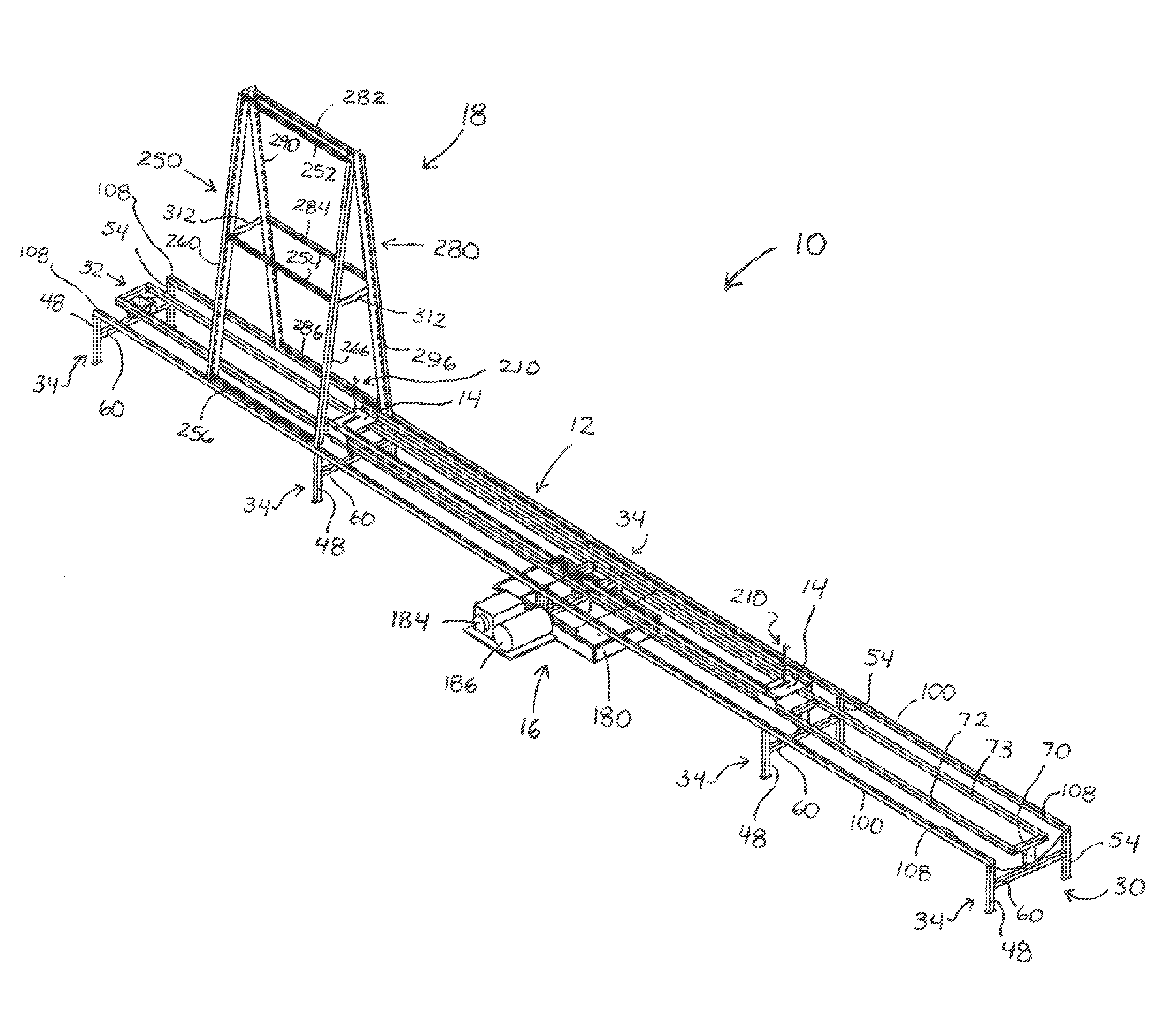
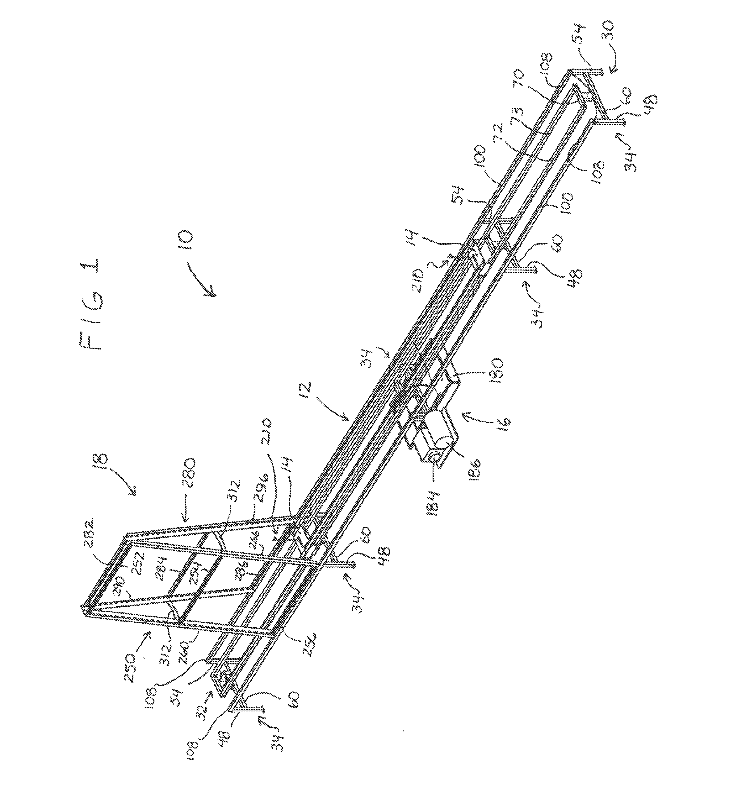
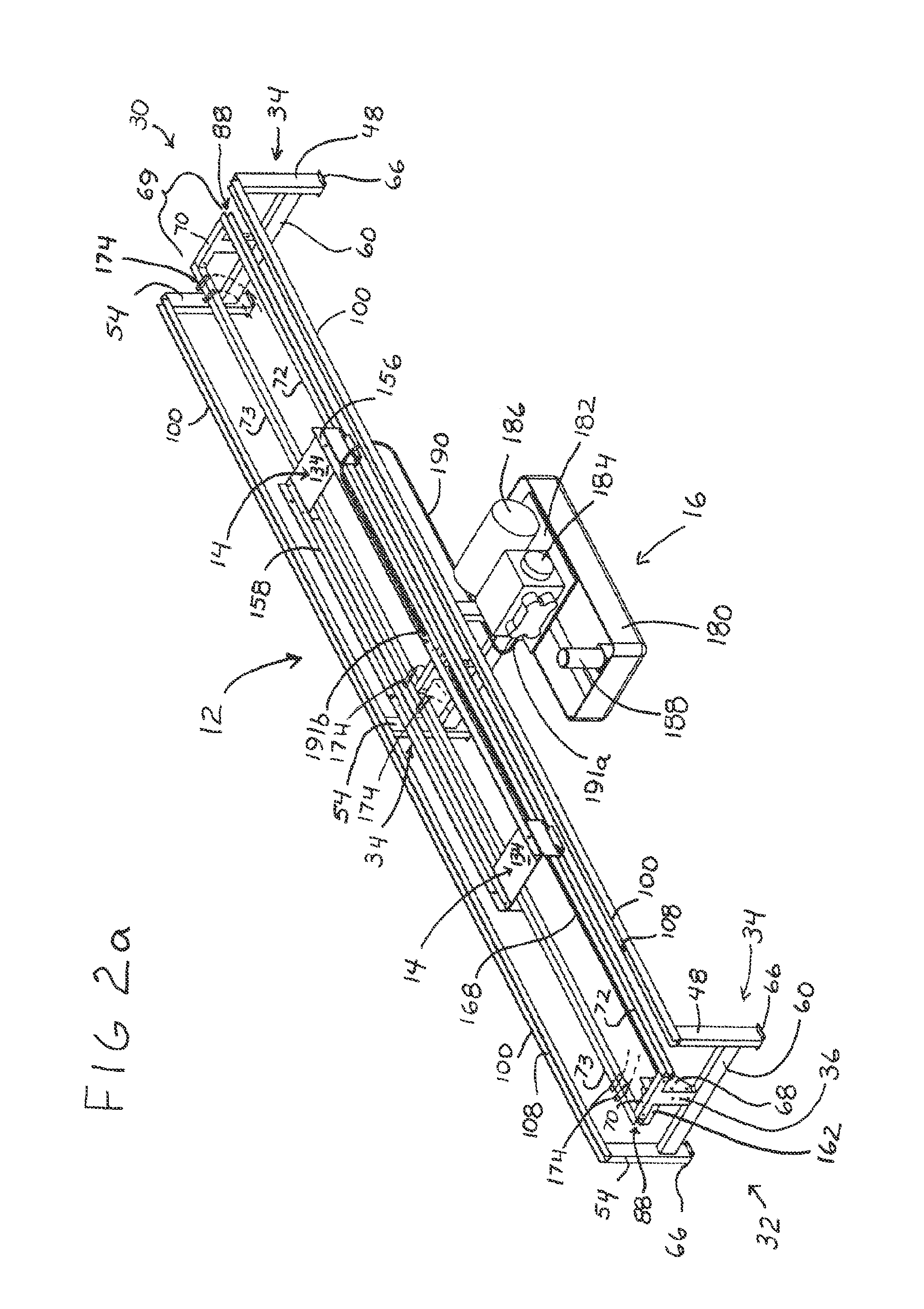
ELEMENT DESCRIPTIONELEMENT #Irrigation system10Framework12Carriage14Carriage assembly15Delivery arrangement16Plant stand18Plant22Shoot24Root26First end30Second end32Sub-frame34Center post36(Center post) upper end38(Center post) lower end40Outer post48, 54(Outer post) upper end50, 56(Outer post) lower end52, 58Cross bar60Opposing ends62, 64Flange66Bracket68Guide assembly69Crossbeam70First end71aSecond end71bGuide member72, 73Base74Side wall76, 82Channel88Rail100Base102Side wall104, 106Slot108Angle110Platform134Strut140, 142First end144Second end146Attachment bar147Friction reducing element148Extension152Connecting element154Link156, 158Drive assembly160Motive source162Drive shaft164Drive member166Belt168Idler roller170Spindle172Sensor174Programmable controller176Reservoir180Platform182Pump184Motive source186Booster pump188Supply line190End191a, 191bFixture194Rotary connector195T-connector196Compressor197Conduit198First end199aTrunk200, 201Connector202, 203Mast204Bottom end205Tr...


PUM


Abstract

An illustrative embodiment of an irrigation system may include a carriage that may move along a predetermined path in a reciprocal manner. The carriage may support one or more exit ports that may be fed nutrient supply by a pressurized delivery arrangement. One or more plant stands may be configured and arranged to straddle the carriage as it moves along the predetermined path. The one or more plant stands may form a chamber into which plant roots may extend, and into which the one or more exit ports may discharge their nutrient supply. The one or more plant stands may include side panels and a cap to reduce infiltration of light and contaminants and to enhance the plant root/nutrient supply interface and absorption rates. The carriage and/or the plant stand(s) may include friction reducing elements that facilitate transverse movement. The carriage and/or the plant stand(s) may be supported by framework.

Description

CROSS REFERENCE TO RELATED APPLICATIONS[0001]Applicant states that this utility patent application claims priority from International Patent Application PCT / US2013 / 032492 filed on Mar. 15, 2013, which claimed priority from provisional U.S. Pat. App. 61 / 657,203 filed on Jun. 8, 2012, and this utility patent application also claims priority from provisional U.S. Pat. App. 61 / 794,599 filed on Mar. 15, 2013 and provisional U.S. Pat. App. 61 / 657,203 filed on Jun. 8, 2012, all of which applications are incorporated by reference herein in their entireties.STATEMENT REGARDING FEDERALLY SPONSORED RESEARCH OR DEVELOPMENT[0002]No federal funds were used to develop or create the disclosed invention.FIELD OF INVENTION[0003]The present invention relates generally to plant cultivation and, more specifically, to apparatuses and methods for use in aeroponic plant growing.DESCRIPTION OF THE PRIOR ART[0004]Improved methods of administering water and / or other nutrients to enhance plant growth have been...

Claims


Application Information

Patent Timeline
IPC IPC(8): A01G31/06A01G31/02
CPCA01G31/02A01G31/06A01G9/247Y02A40/25Y02P60/21A01G9/249A01G7/045A01G29/00A01G31/00A01G22/00
Inventor ANDERSON, DANAJAMES, ALLEN
Owner LIVING GREENS FARM
Why Eureka
Try Eureka