
FIXED ARRAY ACFs WITH MULTI-TIER PARTIALLY EMBEDDED PARTICLE MORPHOLOGY AND THEIR MANUFACTURING PROCESSES

a technology of anisotropic conductive films and manufacturing methods, which is applied in the direction of insulated conductors, cables, conductors, etc., can solve the problems of increasing the probability of short circuit or undesirable high-conductivity in the insulating area between two bonding pads, limiting the particle density of such a dispersion system, and achieving better contact resistance. , the effect of improving the peeling force and reducing the number of particles

Inactive Publication Date: 2014-05-22
TRILLION SCI INC
View PDF2 Cites 21 Cited by
  • Summary
  • Abstract
  • Description
  • Claims
  • Application Information

AI Technical Summary

Benefits of technology

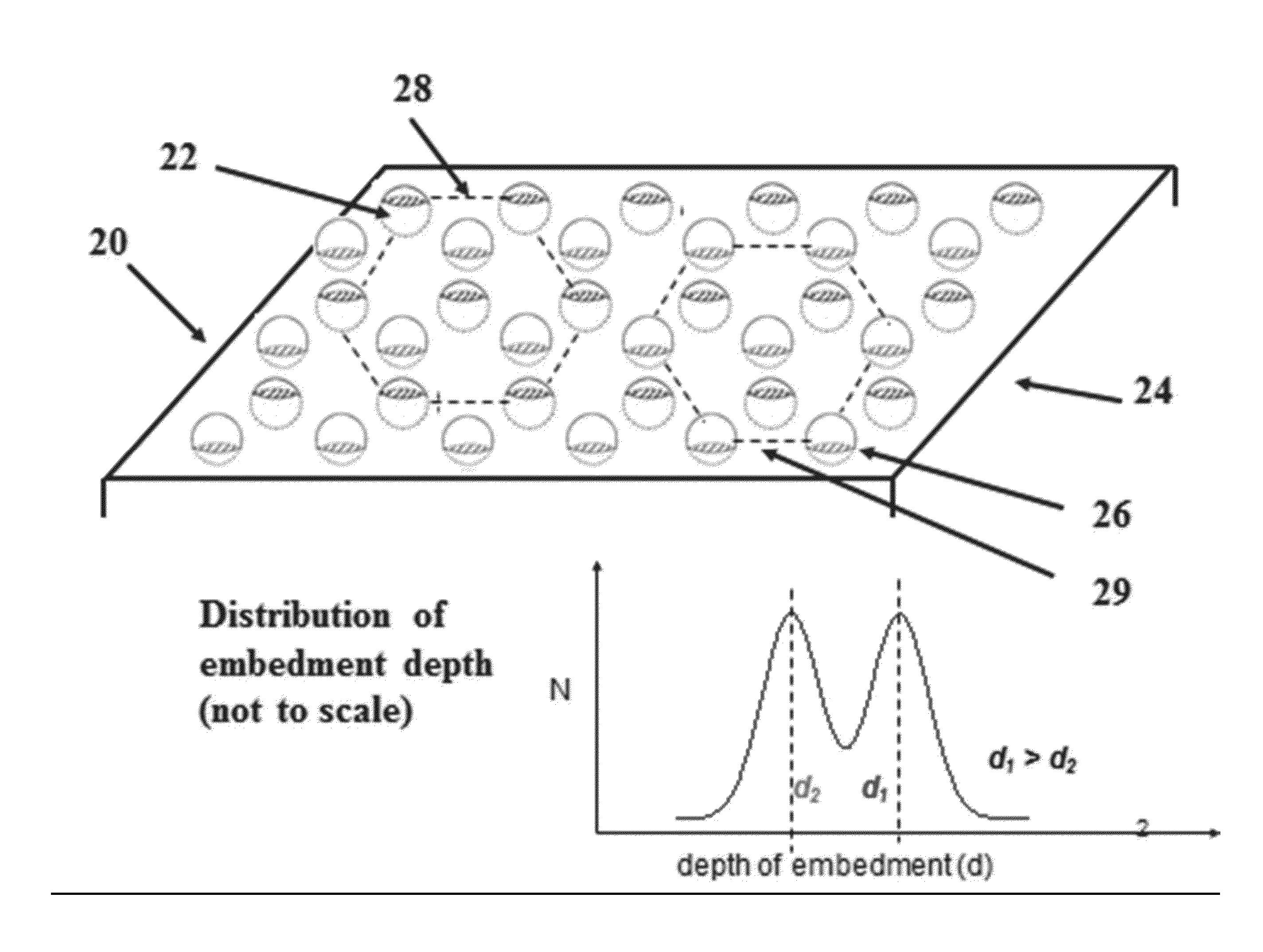
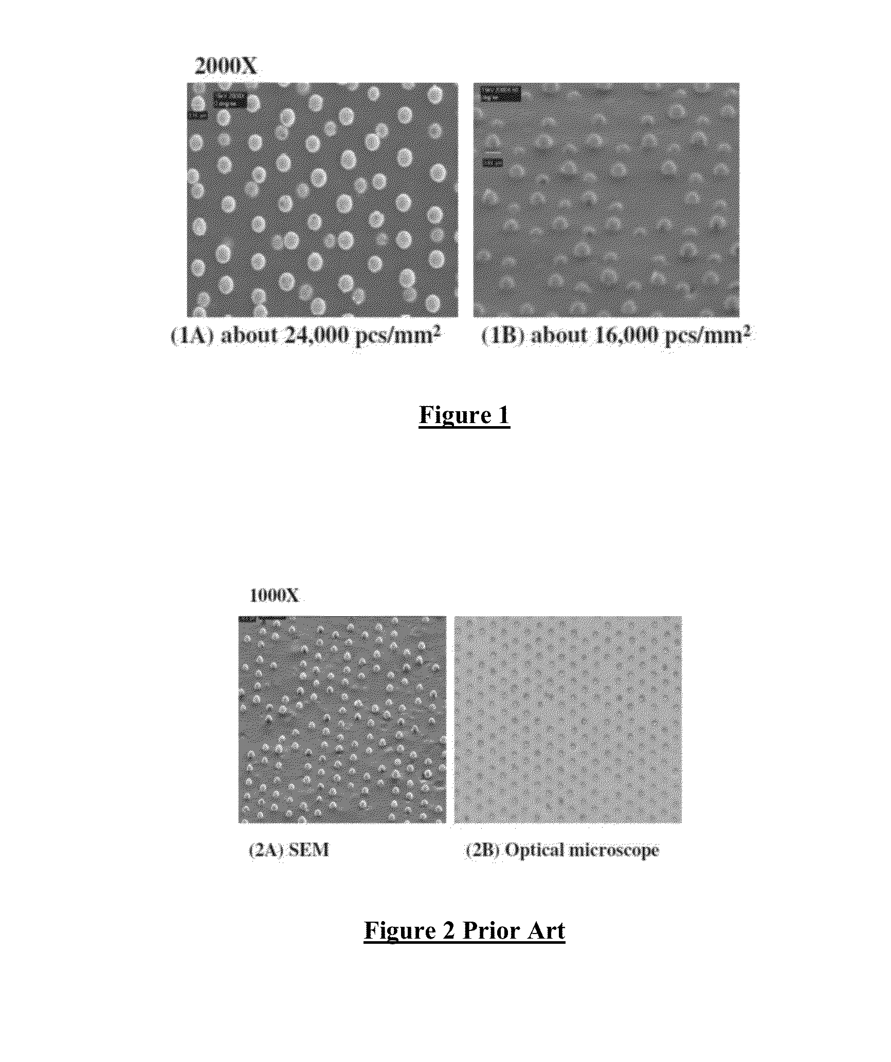
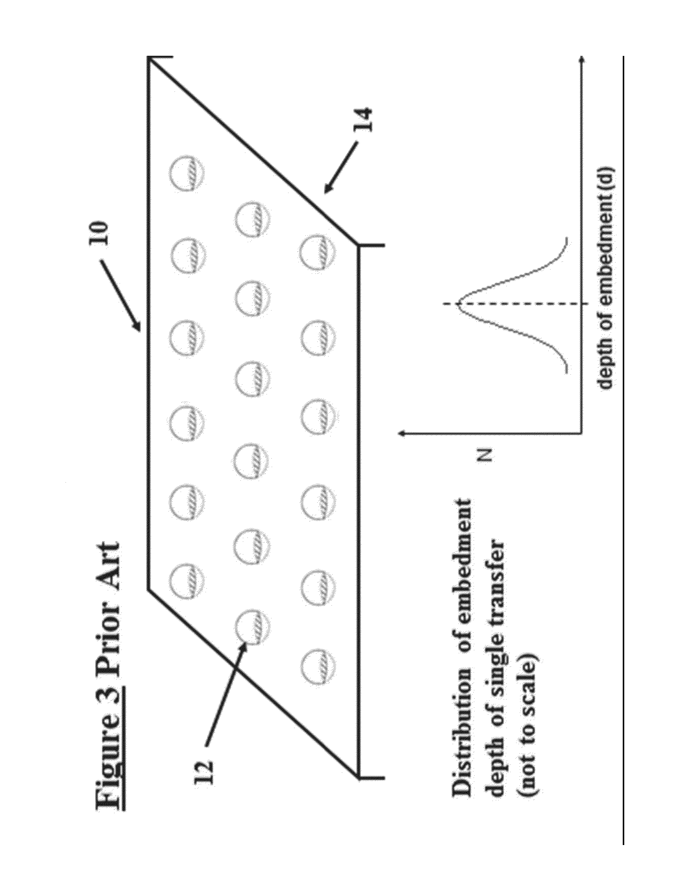
The patent text discusses the results of a study that compared two types of adhesive films. The study found that the adhesive with the two-tier particle morphology had a higher particle capture rate, lower contact resistance, and higher peeling force, even though it had a slightly lower particle density. This two-tier particle morphology was maintained even after the adhesive was stored for more than three months. The study suggests that this adhesive design reduces turbulence during bonding and increases the local effective bonding pressure on the contact particles, resulting in fewer particles being flushed out of the connecting electrodes and stronger adhesion.

Problems solved by technology

There is a limitation on the particle density of such a dispersion system due to X-Y conductivity.
Most of the particles are actually flushed out to the spacing area between electrodes and in some case result in undesirable shorts in the X-Y plane of the ACF.
However, the probability of a short circuit or undesirable high-conductivity in the insulating area between two bonding pads also increases due to the high density of conductive particles and the characteristics of random dispersion.

Method used


Image

  • FIXED ARRAY ACFs WITH MULTI-TIER PARTIALLY EMBEDDED PARTICLE MORPHOLOGY AND THEIR MANUFACTURING PROCESSES
  • FIXED ARRAY ACFs WITH MULTI-TIER PARTIALLY EMBEDDED PARTICLE MORPHOLOGY AND THEIR MANUFACTURING PROCESSES
  • FIXED ARRAY ACFs WITH MULTI-TIER PARTIALLY EMBEDDED PARTICLE MORPHOLOGY AND THEIR MANUFACTURING PROCESSES

Examples


Embodiment Construction

[0028]U.S. Published Application 2010 / 0101700 and U.S. application Ser. No. 13 / 111,300 filed May 19, 2011 to Liang et al. are incorporated herein in their entirety by reference.

[0029]A microcavity array containing microcavities of about 6 μm (diameter) by about 4 μm (depth) by about 3 μm (partition) that is useful in transferring the conductive particles to the surface of the adhesive layer can be prepared by laser ablation on an approximately 2 to 5 mil heat-stabilized polyimide (PI) or a polyester film such as PET to form the microcavity carrier. The microcavity array web is coated with a conductive particle dispersion using a smooth rod. More than one filling may be employed to assure no unfilled microcavities. See Liang '300 and Liang '700.

[0030]The two-tier (or multi-tier) ACF may be obtained by a double (or multiple) transfer process. In one embodiment, an adhesive (preferably an epoxy adhesive) is coated on a release liner and two microcavity films are prepared according to t...


PUM

PropertyMeasurementUnit
thickaaaaaaaaaa
thickaaaaaaaaaa
widthaaaaaaaaaa

Abstract

An anisotropic conductive film (ACF) comprising: (a) an adhesive layer having a substantially uniform thickness; and (b) a plurality of conductive particles individually adhered to the adhesive layer, wherein the conductive particles include a first non-random array of particle sites partially embedded at a first depth within the adhesive layer and a second fixed non-random array or dispersion of conductive particles partially embedded at a second depth or a dispersion of conductive particles fully embedded within the adhesive layer, wherein the first depth and the second depth are distinctly different. The ACF may be supplied as a sheet, a continuous film or as a roll and the multi-tier morphology may be present throughout the length of the product or in select areas.

Description

BACKGROUND[0001]This disclosure relates generally to structures and manufacturing methods for anisotropic conductive films (ACF) with multi-tier partially embedded particles. More particularly, this disclosure relates to structures and manufacturing processes for an ACF having improved particle capture, contact resistance and peeling strength in which one or more non-random arrays of conductive particles are partially embedded at two or multiple distinct depths in the ACF thereby making them readily accessible for bonding to an electronic device. The term “depth” refers to the portion of the particle diameter that is below the top surface of the ACF adhesive. The disclosure also relates to ACFs in which the foregoing advantages are available at lower average particle density than in ACFs without the two tier construction.[0002]Anisotropic Conductive Films (ACF) are commonly used in flat panel display driver integrated circuit (IC) bonding. A typical ACF bonding process comprises a f...

Claims


Application Information

Patent Timeline
Patent Type & Authority Applications(United States)
IPC IPC(8): H01B7/00C09J7/20
CPCH01B7/00B32B5/16B32B7/10B32B2264/00H05K3/323C09J9/02C08K7/16C09J2203/326C08K7/04C08K2201/001C08K2201/005C09J7/20Y10T428/24C09J2301/408
Inventor LIANG, RONG-CHANGAUNG, MAUNG KYAWSUN, YUHAOMA, AN-YU
Owner TRILLION SCI INC
Learn More