
Electric supercharging device and multi-stage supercharging system

Active Publication Date: 2014-05-29
MITSUBISHI HEAVY IND ENGINE & TURBOCHARGER LTD
View PDF8 Cites 32 Cited by
  • Summary
  • Abstract
  • Description
  • Claims
  • Application Information

AI Technical Summary

Benefits of technology

This patent introduces a cooling system for motors using external air. The system cools down areas that tend to get hot, such as the stator and motor coil, without needing a separate pump to bring in the air. This results in better cooling with a simple system. The cooling system uses the negative pressure of the compressor, which means the air is not heated up before being introduced. The outside air is not compressed, so it helps to cool the motor more effectively. This patent simplifies and improves motor cooling with a more efficient and cost-effective design.

Problems solved by technology

However, the supercharging pressure is decreased when the engine speed is low in the turbocharger.
And sufficient increase of the output cannot be expected.
Since a rotor of the electric motor is generally provided with convex-shaped pole on its surface, as the motor rotation speed increases, a substantial amount of windage loss occurs due to the irregular surface shape.
This can cause not only the power loss of the electric motor but wind nose caused by the rotor, which can lead to the noise increase.
In order to reduce this power loss and noise, design change of the rotor may be considered, but there is a limit to this in reality.

Method used


Image

  • Electric supercharging device and multi-stage supercharging system
  • Electric supercharging device and multi-stage supercharging system
  • Electric supercharging device and multi-stage supercharging system

Examples


first embodiment

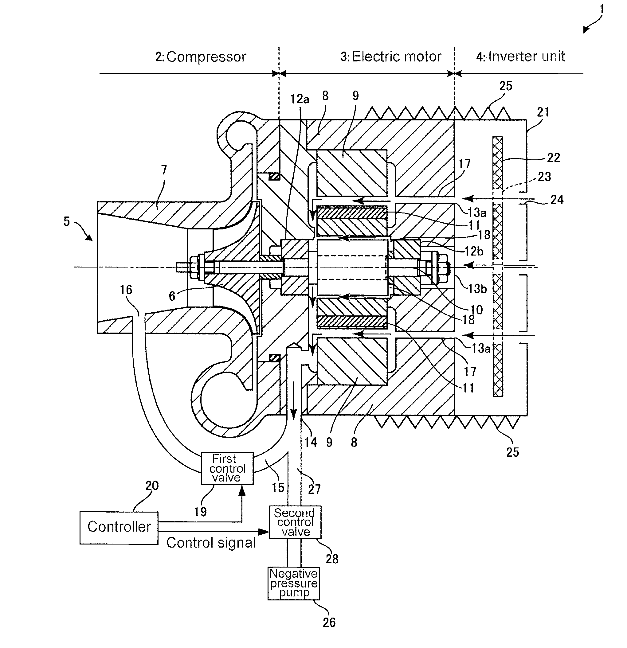
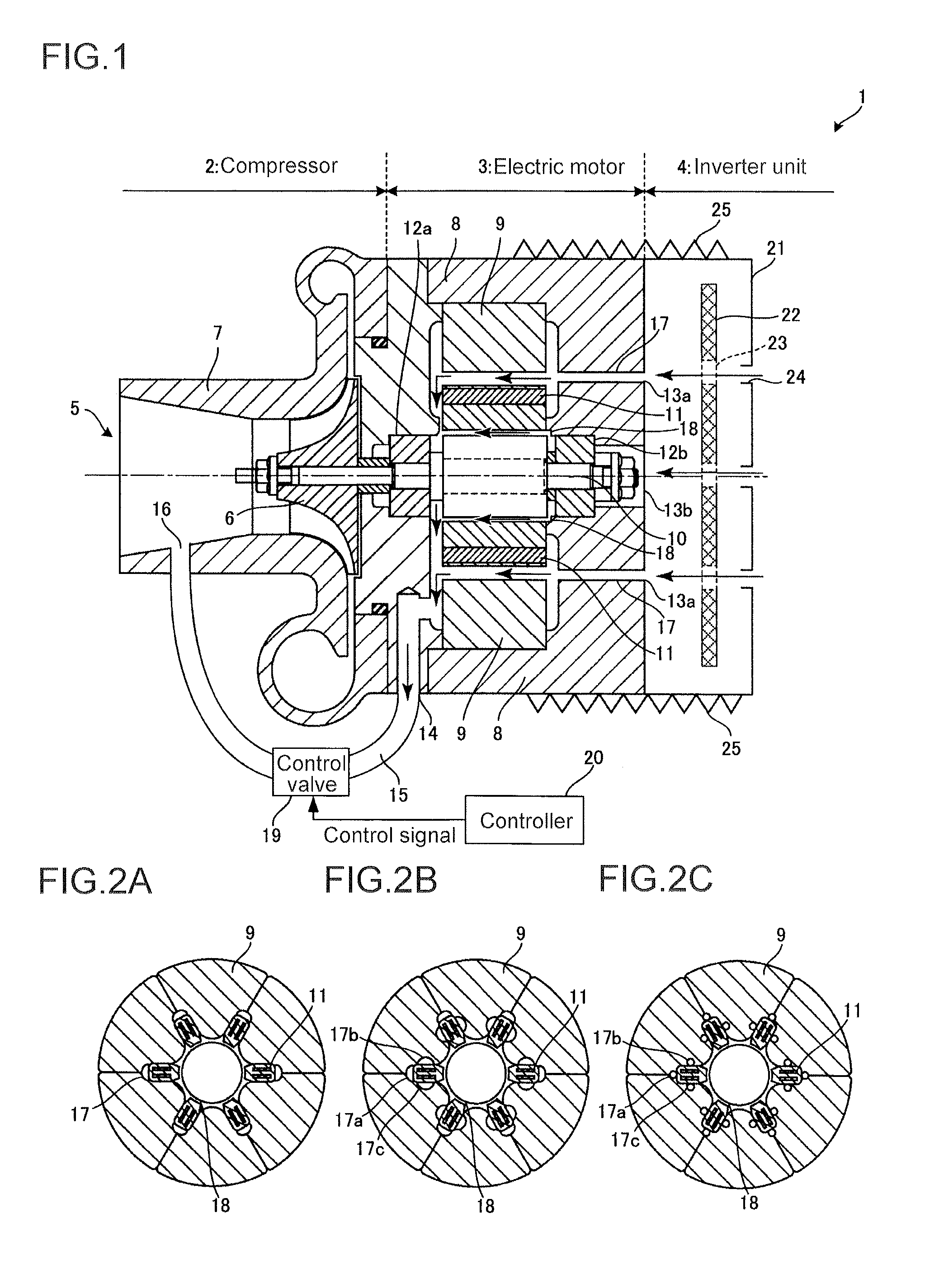
[0028]FIG. 1 is a cross-sectional view of an overall configuration of an electric supercharging apparatus 1 according to a first embodiment. The electric supercharging apparatus 1 is provided with a compressor 2 for supercharging gas, an electric motor 3 for driving the compressor 2 and an inverter unit 4 functioning as an inverter for control of the electric motor 3. The inverter unit 4 obtains DC current power from a battery (not shown) and changes the current and voltage applied to the electric motor 3 so as to control the rotation speed of the electric motor 3.

[0029]The inverter unit 4 and the electric motor 3 are integrally connected so as to reduce the distance between the inverter unit 4 and the electric motor 3, thereby minimizing electrical loss of the power supplied to the electric motor 3. In the case where the electrical loss is not an issue, the electric motor 3 and the inverter unit 4 may be arranged away from each other as separate units.

[0030]In the compressor 2, the...

second embodiment

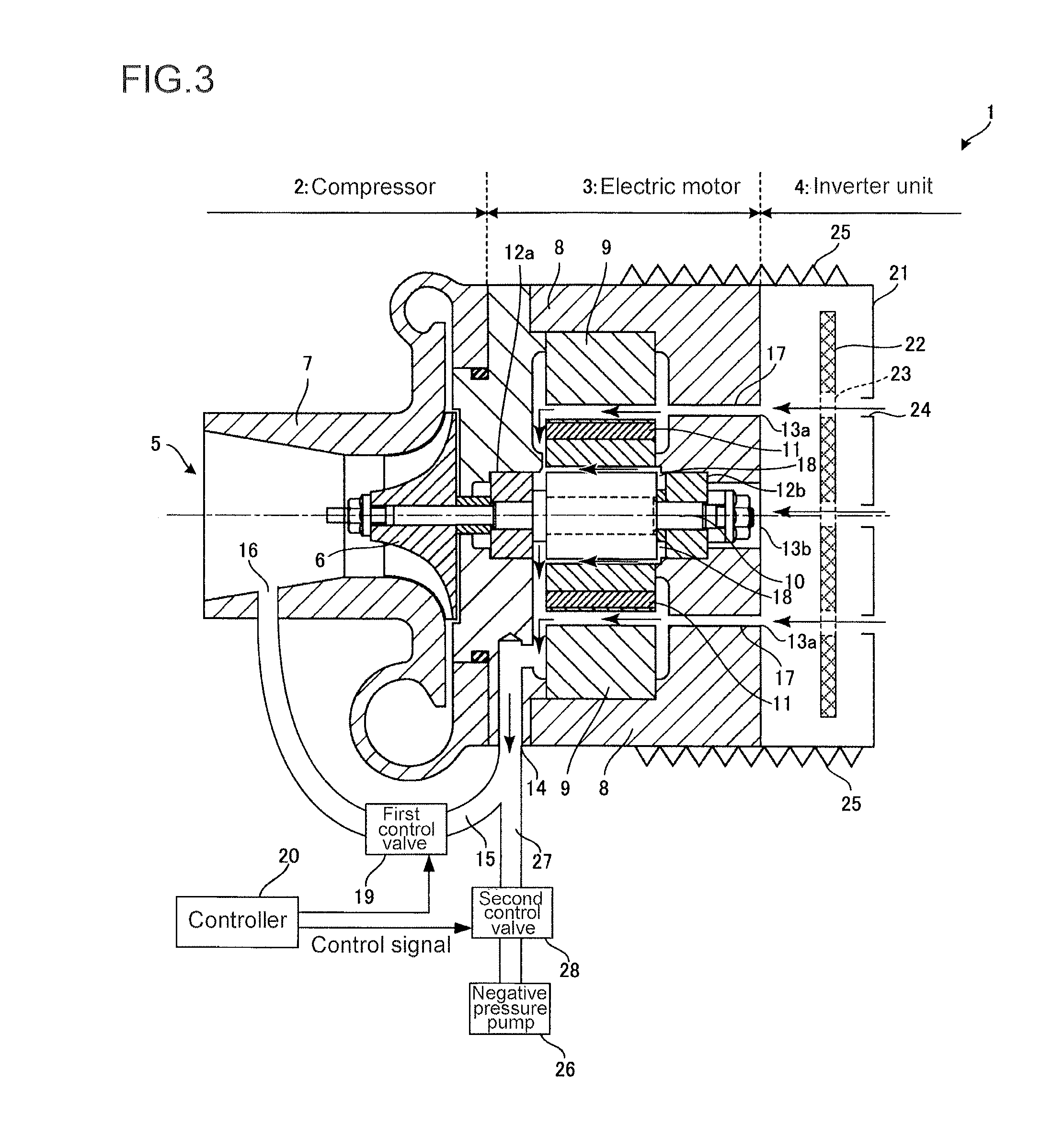
[0056]FIG. 3 is a cross-sectional view of the overall configuration of the electric supercharging apparatus 1 according to a second embodiment. In the following embodiments, components already described in reference to the first embodiment are denoted by the same reference numerals, and thus detailed description thereof is appropriately omitted.

[0057]In the second embodiment, an auxiliary vacuum pump 26 not shown (hereinafter referred to as “negative pressure pump 26”) for the engine (not shown) to which the electric supercharging apparatus 1 supercharges, the negative pressure is supplied to the gas exhaust port 14 and the outside air is introduced into the first cooling passage 17 and the second cooling passage 18 to perform the cooling. The negative pressure pump 26 is connected to the gas discharge port 14 via the second intake passage 27, and a second control valve 28 is for adjusting an opening degree is provided in the second intake passage 27. Together with the first control...

third embodiment

[0060]Next, in reference to FIG. 4, explained is the case where the electric supercharging apparatus 1 according to the present invention is applied to an electric e-stage supercharging system configured by combining the electric supercharging apparatus 1 according to the present invention with a turbocharger 110 which is driven by the exhaust gas from an engine 100. FIG. 4 is a block diagram of an overall configuration of the electric 2-stage supercharging system according to a third embodiment.

[0061]The electric 2-stage supercharging system according to the present embodiment comprises a turbocharger 110 on a low pressure side (a downstream side) as a supercharging unit for the engine 100. The turbocharger 110 has a compressor 112 which operates in conjunction with an exhaust turbine 111 driven by the exhaust gas from the engine 100. Further, the electric supercharging apparatus 1 which is powered by the electric motor described in the above embodiments is provided on a high press...


PUM


Abstract

It is intended to provide: an electric supercharging apparatus wherein, with a simple structure, rotor windage loss in an electric motor for driving a compressor is reduced and good cooling performance is produced; and a multi-stage supercharging system using the electric supercharging device. This electric supercharging apparatus is provided with: a first cooling passage formed in a stator along a motor coil and communicating a gas supply port with a gas discharge port in a motor housing; and a first intake passage connecting the gas discharge port to an intake port of a compressor. This electric supercharging apparatus is configured to introduce outside air into the first cooling passage via the gas supply port by applying negative pressure to the first cooling passage via the first intake passage, thereby cooling the inside of the motor housing.

Description

TECHNICAL FIELD[0001]The present invention relates to the technical field of an electric supercharging device for supercharge of an internal combustion engine such as an engine by being driven by an electric motor for, and of a multi-stage supercharging using the electric supercharging device.BACKGROUND ART[0002]In an internal combustion engine such as an engine, there is a case where the intake air is compressed and supplied using a supercharging apparatus such as a turbocharger, thereby increasing output. As one type of this supercharging apparatus, there is a turbocharger which is configured to rotate a turbine at high speed using energy of the exhaust gas and drive a centrifugal compressor by the rotational force so as to feed the compressed air into the engine. However, the supercharging pressure is decreased when the engine speed is low in the turbocharger. And sufficient increase of the output cannot be expected. On the other hand, the electric supercharging apparatus which h...

Claims


Application Information

Patent Timeline
IPC IPC(8): F02B39/00F02B39/16F02B39/10
CPCF02B39/005F02B39/16F02B39/10F02B37/04F02B37/16F02B37/18F02B33/40H02K5/1732H02K7/14H02K9/06H02K11/33Y02T10/12F04D17/10F04D29/4206F04D29/5806
Inventor AN, BYEONGILEBISU, MOTOKISUZUKI, HIROSHI
Owner MITSUBISHI HEAVY IND ENGINE & TURBOCHARGER LTD
Learn More