Common mode noise chip filter and method for manufacturing the same

a technology of noise chip and filter, which is applied in the direction of waveguide type devices, inductances, antennas, etc., can solve the problems of reducing the service life of the filter, and increasing the noise rather than confirming the noise type, so as to improve the permeability and the effect of reducing internal stress and excellent reliability

Inactive Publication Date: 2014-05-29
SAMSUNG ELECTRO MECHANICS CO LTD
View PDF4 Cites 7 Cited by
  • Summary
  • Abstract
  • Description
  • Claims
  • Application Information

AI Technical Summary

Benefits of technology

[0016]An object of the present invention is to provide a common mode noise chip filter having excellent reliability by changing a structure

Problems solved by technology

Electronic devices in our environment are sources of radiation noise, to a greater or lesser degree.
The inductor allows direct current to flow well therethrough, but the inductor has high impedance (resistance against alternating current) and thus alternating current does not flow well through the inductor.
Even though parts for noise prevention measures are added to a circuit, noise is rather increased without confirming the type of noise.
In addition, since the common mode noise is transferred to the ground or the like

Method used


Image

  • Common mode noise chip filter and method for manufacturing the same
  • Common mode noise chip filter and method for manufacturing the same
  • Common mode noise chip filter and method for manufacturing the same

Examples


example 1

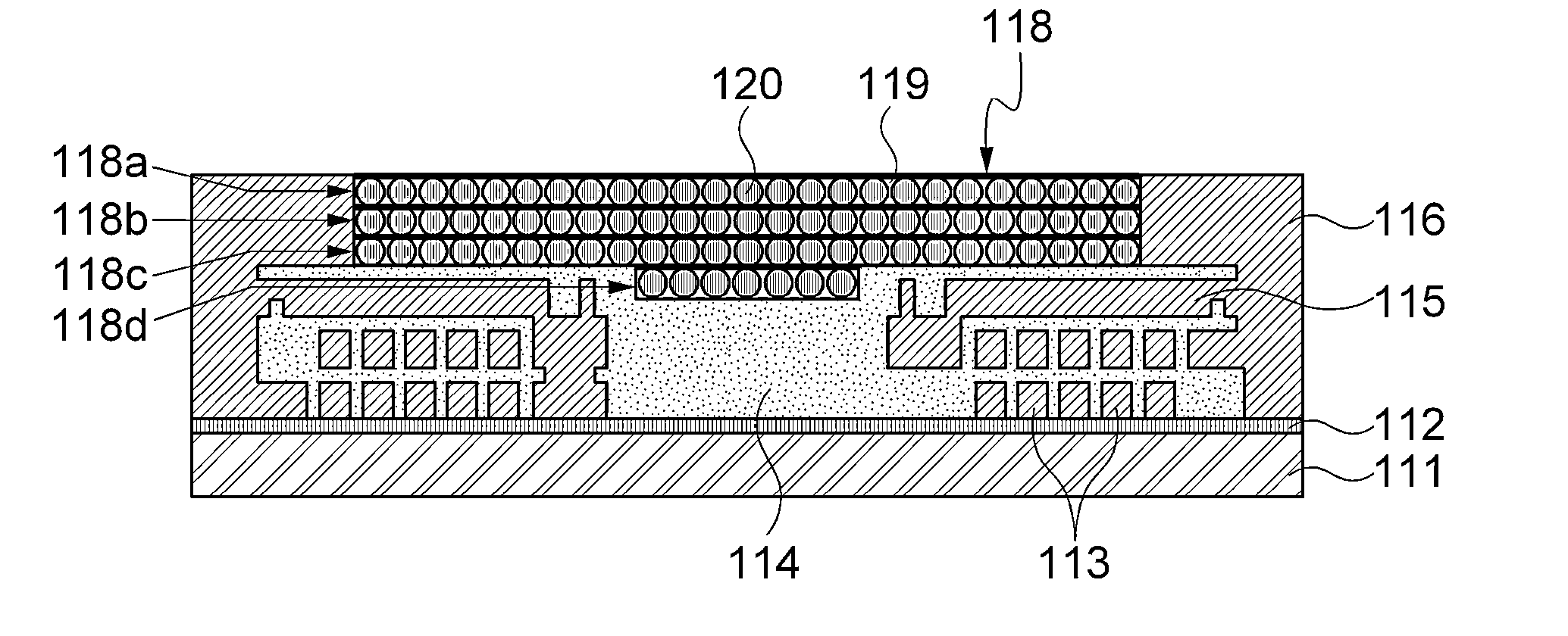
[0076]A ferrite dispersion liquid was prepared by dispersing a spherical ferrite powder (NiZnCu ferrite) having a diameter of 5 μm and a small amount of dispersant (BYK2155) in a solvent (ethanol). The weight ratio of the solvent and the ferrite powder was 10:8. The dispersant was added in a concentration of 2 wt % based on the weight of the ferrite powder.

[0077]The ferrite dispersion liquid filled a cavity of the resultant substrate having copper internal electrode coil patterns formed therein. Then, a solvent in the ferrite dispersion liquid was evaporated.

[0078]After all the solvent was evaporated, an epoxy resin having low viscosity of 1˜5 cps was injected thereinto by using a micropipette, to form one ferrite-polymer complex layer having a thickness of 5 μm. Then, heat was applied to the ferrite-polymer complex layer, to harden the epoxy resin.

[0079]After hardening the epoxy resin, processes of filling with ferrite dispersion liquid, evaporating solvent, injecting epoxy resin t...

example 2

[0081]A common mode noise chip filter was manufactured by the same procedure as Example 1, except that a flake ferrite powder having a diameter of 20 μm was used and a ferrite-polymer complex layer having five layers of which each has a thickness of 20 μm.

experimental example

Confirmation on Inner Structure after Lead Heat-Resistance Test

[0083]The common mode noise chip filters manufactured according to Examples 1 and 2 and Comparative Example 1 were dipped in a lead (Pb) bath of 300° C. three times for 10 seconds, and then internal structures thereof were confirmed. The confirmation results were shown in FIGS. 5 to 8.

[0084]Referring to FIGS. 5 and 6 showing the internal structure of the noise chip filter according to Comparative Example 1, in the case where the ferrite-polymer complex layer was formed to have a single-layer structure like the related art, cracks (square marks) occurred inside the ferrite-polymer composite layer.

[0085]However, referring to FIGS. 7 and 8 showing internal pictures of Examples 1 and 2 in which the ferrite-polymer complex layer was formed to have a multilayer structure like the present invention, it was confirmed that cracks or defects did not occur inside the ferrite-polymer composite layer.

[0086]As set forth above, accordi...


PUM

PropertyMeasurementUnit
Thicknessaaaaaaaaaa
Thicknessaaaaaaaaaa
Particle sizeaaaaaaaaaa

Abstract

Disclosed herein are a common mode noise chip filter and a method for manufacturing the same, the common mode noise chip filter including: a ferrite substrate; coil patterns formed on the ferrite substrate; and a ferrite-polymer complex layer formed on the result substrate having the coil patterns formed therein, wherein the ferrite-polymer complex layer has a multilayer structure, so that the ferrite-polymer complex layer filling an inner space of the substrate having inner coil patterns is formed to have the multilayer structure but not a single-layer structure, thereby lowering internal stress, and thus improving reliability of the common mode noise chip filter as a product.

Description

CROSS REFERENCE(S) TO RELATED APPLICATIONS[0001]This application claims the benefit under 35 U.S.C. Section 119 of Korean Patent Application Serial No. 10-2012-0137050, entitled “Common Mode Noise Chip Filter and Method for Manufacturing the Same” filed on Nov. 29, 2012, which is hereby incorporated by reference in its entirety into this application.BACKGROUND OF THE INVENTION[0002]1. Technical Field[0003]The present invention relates to a common mode noise chip filter and a method for manufacturing the same.[0004]2. Description of the Related Art[0005]Electronic devices in our environment are sources of radiation noise, to a greater or lesser degree. Since the noise is freely transformed and appears briefly and then vanishes as described above, there is a need for measures to prevent the electronic device itself from being a source of noise and resistance (immunity) measures to prevent occurrence of malfunction due to even foreign noise. This is a fundamental thought of EMC.[0006]G...

Claims


Application Information

Patent Timeline
IPC IPC(8): H03H7/01
CPCH03H3/00H03H7/0138H01F17/0013H01F2017/0066H01F2017/0093H03H1/0007H03H2001/0057H03H2001/0092Y10T29/49016H01F41/00H01F17/00
Inventor BAE, JUN HEELEE, SANG MOONWI, SUNG KWONKIM, YONG SUK
Owner SAMSUNG ELECTRO MECHANICS CO LTD
Why Eureka
Try Eureka