Cuvette for light scattering measurements incorporating evaporation inhibition means

a technology of light scattering and cuvettes, applied in the direction of measuring devices, instruments, sampling, etc., can solve the problems of large change in the height of the fluid level, deleterious effects on the sample itself, and significant amount of sample still required to deliver

Active Publication Date: 2014-05-29
WYATT TECH
View PDF14 Cites 16 Cited by
  • Summary
  • Abstract
  • Description
  • Claims
  • Application Information

AI Technical Summary

Problems solved by technology

The flow mode alternative might require a lower sample volume within the flow cell itself, however, a significant amount of sample is still required to deliver and fill the measurement volume of the cell.
Partial evaporation of the solvent from a cuvette produces an effective increase of the dissolved solute concentration which additionally may have deleterious effects on the sample itself.
More substantial evaporation of the sample solvent may prevent any type of LS measurement, a problem particularly prevalent in very small volume cuvettes where even a small amount of evaporation results in a large change in the height of the fluid level.
This can cause the meniscus to be intersected by the incident light beam, overwhelming the detector or detectors and distorting significantly any measurements.
Further, temperature dependent measurements during which the cuvette environment is cycled over a broad range of ambient temperatures may promote evaporation thus skewing the results and giving inaccurate data regarding temperature dependent reactions, such as molecular interaction experiments.
However, for light scattering measurements, both of these commonly used evaporation mitigation techniques can be problematic.
With respect to the cap, the sample solvent may still evaporate and condense on th

Method used


Image

  • Cuvette for light scattering measurements incorporating evaporation inhibition means
  • Cuvette for light scattering measurements incorporating evaporation inhibition means
  • Cuvette for light scattering measurements incorporating evaporation inhibition means

Examples


Embodiment Construction

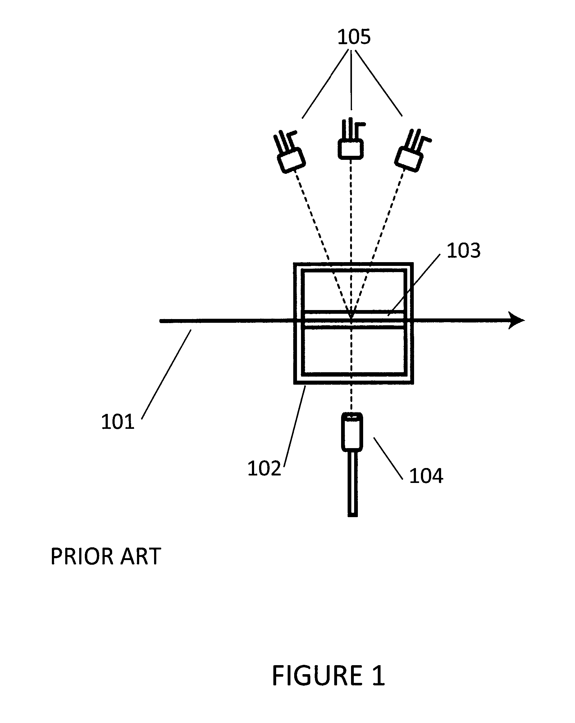
[0015]Cuvettes can be suitable sample vessels for the measurement of both Dynamic Light Scattering (DLS) and Static Light Scattering (SLS) at a single or multiple angles (MALS). A cutaway top view of a cuvette arranged for such light scattering measurements is shown in FIG. 1. A light beam 101, generally produced by a laser, is directed into the cuvette body 102, through an optically transparent surface, thereby passing through the sample contained within the sample measurement chamber 103. For the case of DLS measurements, a light scattering detector 104, generally an avalanche photodiode (APD) coupled to a light fiber, is used to collect scattered light. SLS measurements may be made at any number of angles by using one or more appropriate photodetectors 105, such as a photodiode, often a silicon PIN photodiode. These SLS and DLS detectors may exist on the same side or on opposite sides of the cuvette from each other or in other configurations. The detectors are generally arranged ...


PUM


Abstract

A cuvette for use with light scattering detectors is disclosed. A trough or moat within the cuvette can be filled with solvent which is not in fluid contact with the sample to be measured. This solvent moat creates saturated vapor pressure in the chamber preventing evaporation from the sample when the cuvette is capped. The cuvette itself may be made of an inexpensive polymer which can be polished to high optical quality while still being moldable in complex forms capable of enabling further utility, such as extra griping surfaces, identification tabs allowing the detection instrument to determine the cuvette model, and various sample chamber forms. The novel cuvette may have extremely small sample volumes, while allowing significant overfill of the measurement chamber, improving ease of sample loading. The polymers used may be relatively inexpensive, and therefore the cuvette can generally be discarded after a single use.

Description

BACKGROUND[0001]Light scattering (LS) is a non-invasive technique for characterizing macromolecules and a wide range of particles in solution. The two types of light scattering detection frequently used for the characterization of macromolecules are static light scattering (SLS) and dynamic light scattering (DLS).[0002]Static light scattering includes a variety of embodiments such as single angle light scattering (SALS), dual angle light scattering (DALS), low angle light scattering (LALS), and multi-angle light scattering (MALS). SLS experiments generally involve the measurement of the absolute intensity of the light scattered from a sample in solution that is illuminated by a fine beam of light. This measurement is often used, for appropriate classes of particles / molecules, to determine the size and structure of the sample molecules or particles, and, when combined with knowledge of the sample concentration, the determination of weight average molar mass. In addition, nonlinearity...

Claims


Application Information

Patent Timeline
IPC IPC(8): G01N21/03
CPCG01N21/03B01L2200/142G01N21/51G01N2021/0378
Inventor TRAINOFF, STEVEN P.DEWEY, MICHAEL W.BERGES, AYM M.
Owner WYATT TECH
Why Eureka
Try Eureka