Medical device with ultrasound transducers embedded in flexible foil

a technology of ultrasound transducers and flexible foils, applied in the field of ultrasound imaging apparatuses, can solve the problems of flexible foils producing acoustic effects adverse to the and achieve the effect of maximizing the acoustic performance of transducer elements

Active Publication Date: 2014-05-29
KONINKLJIJKE PHILIPS NV
View PDF12 Cites 28 Cited by
  • Summary
  • Abstract
  • Description
  • Claims
  • Application Information

AI Technical Summary

Benefits of technology

[0015]In some other embodiments the one or more conductive layers is one layer deposited on the bottom surface of the flexible foil and on the bottom surface of the one or more piezoelectric elements. This provides great advantages for protection of the electrical signal of the transducer from adverse external perturbations and is useful in the realization of the Faraday cage around the bottom electrode avoiding RF signal interference with ultrasound signal during ablation.
[0019]In placing the ultrasound transducer assembly onto the base structure, the openings of the flexible foil in which the piezoelectric elements are fasten, e.g. by means of glue, are located in positions corresponding to the cavities of the base structure. The back side or bottom surface of the piezoelectric elements is therefore accessible though the cavities of the base structure. The modality of addition of the backing material allows for freedom and good control of the appropriate choice of the material. For example, the filling material can be dispensed into the cavities by injection in a fluidic state through conducts in the base structure. Examples of filling materials comprises adhesive which can rapidly bond to plastics and metal upon exposure to UV and / or visible light. Filling materials compositions may also comprise microspheres, such as ceramic or glass sphere, which can be hollow, lightweight and with a high compressive strength.
[0021]The invention is of great advantage in particular in the fabrication of high frequency (HF) transducers. In traditional HF transducers, the flexible foil is included in the transducer stack and the transducer elements are place onto the flexible foil. As the higher the frequency, the lower the thickness of the piezoelectric elements, traditional HF transducers have a high chance of failure due to high risk of breakdown as the electrodes from the front side and the backside of the piezoelectric material are becoming too close with respect to each other. The invention, by embedding the piezoelectric elements into the flexible foil, provides a solution which is therefore particularly advantageous for HF transducers.
[0024]In some other embodiments the ultrasound transducer assembly according to the first aspect of the invention further comprises an isolation layer deposited onto the external surface of the ultrasound transducer assembly. This electrical isolation layer may be a matching layer coating the ultrasound transducer assembly for maximizing the acoustic performance of the transducer elements.

Problems solved by technology

However, as the flexible substrate is part of the material stack forming the assembly, the flexible foil may produce acoustical effect adverse to the transducer elements performance.

Method used


Image

  • Medical device with ultrasound transducers embedded in flexible foil
  • Medical device with ultrasound transducers embedded in flexible foil
  • Medical device with ultrasound transducers embedded in flexible foil

Examples


Embodiment Construction

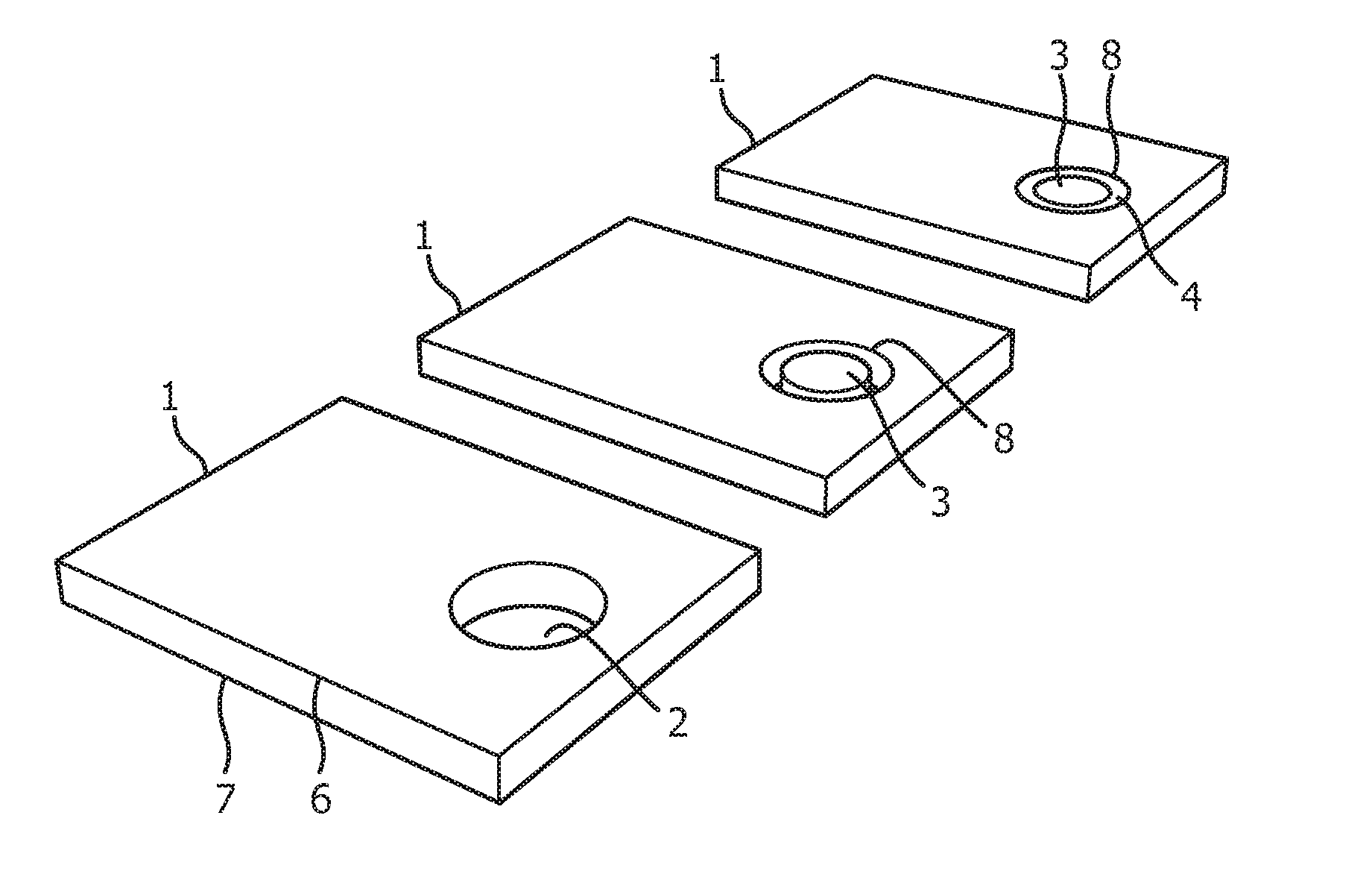
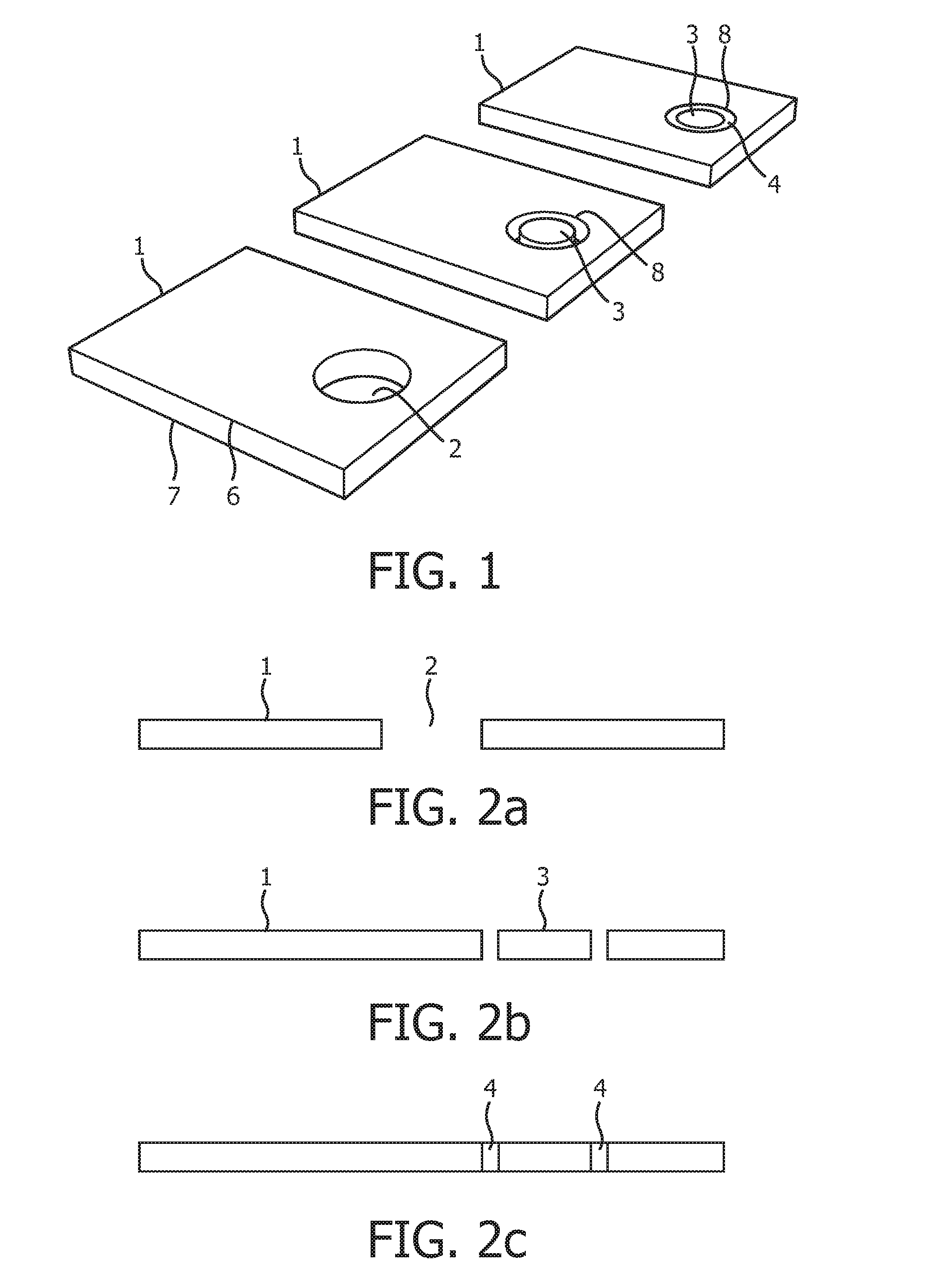
[0056]FIG. 1 shows three steps of the method for fabricating an ultrasound transducer according to one aspect of the invention. On the flexible foil 1 a desired patterned is produced, e.g. opening 2, extending from the top surface 6 to a bottom surface 7. Piezoelectric elements, e.g. piezoelectric element 3, are located in into the openings, e.g. opening 2 and fastened to the internal rim 8 of opening 2. Non-conductive glue 4 may be used to fasten the piezoelectric element 3 to the internal rim 8 of opening 2.

[0057]FIG. 2a shows a cross section of the flexible foil 1 before including the piezoelectric elements. The opening 2 is filled, as shown in FIG. 2b by a piezoelectric element 3. The mounting of the piezoelectric element 3, e.g. a piezoelectric patch, is achieved by gluing the patches in the designated areas at the rim or edge of the opening 2. In some embodiments the mounting of the piezoelectric element 3 may be achieved by gluing a thin peripheral annular region of the piezo...


PUM

PropertyMeasurementUnit
flexibleaaaaaaaaaa
piezoelectricaaaaaaaaaa
electrical isolationaaaaaaaaaa

Abstract

The invention relates to ultrasound imaging method and apparatus suitable for minimally invasive ultrasound diagnostic devices in cardiac ablation monitoring and in tumor ablation monitoring. The present invention proposes to manufacture a transducers assembly and system on a patterned flexible foil by embedding transducers patches in apertures on the foil surface. This provides great control of the acoustic properties of the transducer.

Description

FIELD OF THE INVENTION[0001]The invention relates to ultrasound imaging apparatus suitable for minimally invasive ultrasound diagnostic devices. The invention can be used for fabrication of interventional devices used in cardiac ablation monitoring and in cancer ablation monitoring.BACKGROUND OF THE INVENTION[0002]Radio frequency (RF) catheter ablation is an invasive procedure used to remove faulty electrical pathways from patients who are prone to develop cardiac arrhythmias such as atrial fibrillation (AF). In AF ablation procedures, complete electrical isolation of the pulmonary veins is targeted and this is achieved by creating lesion lines with an ablation catheter.[0003]The majority of the catheter ablation procedures are performed with “single-point ablation catheters”. Lesion lines can be created with such catheters by sequential point by point ablation. To achieve complete electrical isolation of the pulmonary veins lesion lines are created meeting the two requirements of b...

Claims


Application Information

Patent Timeline
Patent Type & Authority Applications(United States)
IPC IPC(8): A61B8/00
CPCA61B8/0883A61B8/12A61B8/445A61B18/1492A61B2018/00738A61B2018/00839B06B1/0629G01S2015/465A61B2034/2063A61B2090/3782A61B34/20A61B2090/364A61B2034/2051Y10T29/42A61B8/4483A61B8/4494A61B2018/00577
Inventor DELADI, SZABOLCSVAN DER VLEUTEN, CORNELIUS ANTONIUS NICOLAAS MARIARADEMAKERS, ANTONIUS JOHANNES JOSEPHUS
Owner KONINKLJIJKE PHILIPS NV
Why Eureka
Try Eureka