Fault diagnosis method, grid interconnection apparatus, and controller

a technology of fault diagnosis and grid interconnection, applied in relays, instruments, transportation and packaging, etc., can solve the problems of waste of labor and cost of users or manufacturers, abnormality is not found at the time of repair by the manufacturer, etc., and achieve the effect of automatically diagnosing the fault related problems

Active Publication Date: 2014-06-12
KYOCERA CORP
View PDF10 Cites 36 Cited by
  • Summary
  • Abstract
  • Description
  • Claims
  • Application Information

AI Technical Summary

Benefits of technology

[0011]With such a feature, after stopping the interconnected operation by detecting abnormality, the grid interconnection apparatus performs an independent operation, thereby making it possible to perform a test to verify whether an output power state of a distributed power source and / or the grid interconnection apparatus is normal. Then, an error process is performed after confirming that the output power state of the distributed power source and / or the grid interconnection apparatus does not satisfy a predetermined condition (that is, not being normal), thereby making it possible to automatically diagnose the fault related to the grid interconnection apparatus even when the interconnected operation is stopped.

Problems solved by technology

The case in which such an error process is performed is treated as a serious fault state, resulting in that the user makes a repair request to a manufacturer through a distributor.
However, when the cause of the above-described error process is a disturbance factor such as lightning strike and instantaneous grid voltage distortion, abnormality is not found at the time of repair by the manufacturer in some cases.
In such a case, labor and cost of the user or the manufacturer are wasted.

Method used


Image

  • Fault diagnosis method, grid interconnection apparatus, and controller
  • Fault diagnosis method, grid interconnection apparatus, and controller
  • Fault diagnosis method, grid interconnection apparatus, and controller

Examples


first embodiment

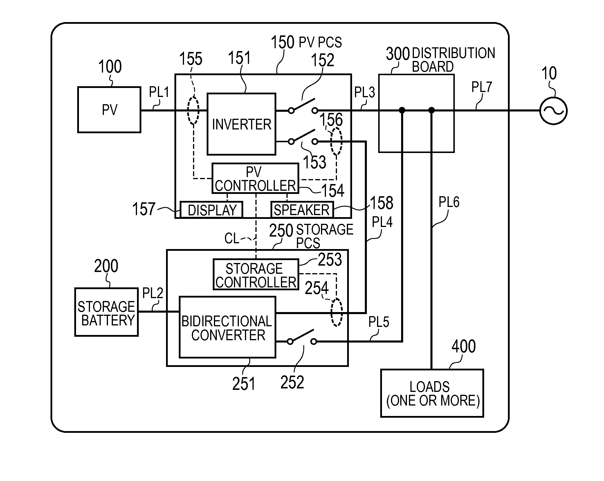
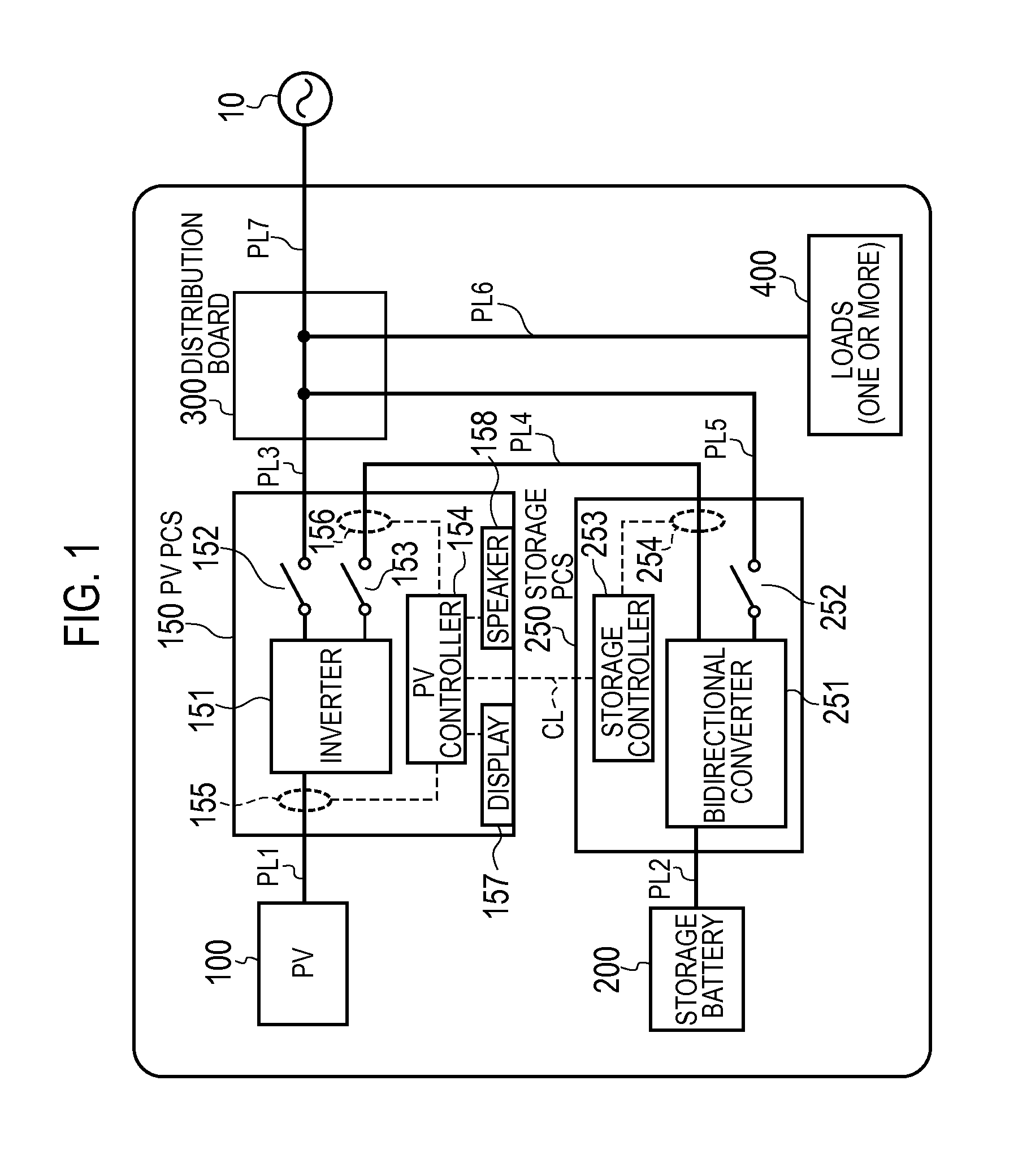
[0023]FIG. 1 is a block diagram of a power control system according to the present embodiment. In the following block diagram, a power line is shown by a thick line, and a communication line (a signal line) is shown by a dashed line. Note that, the communication line may not be limited to be wired but may be wireless.

[0024]As shown in FIG. 1, the power control system according to the present embodiment is provided with a photovoltaic cell (a PV) 100, a PV power conditioner (a PV PCS) 150, a storage battery 200, a storage power conditioner (a storage PCS) 250, a distribution board 300, and one or more loads 400 at a consumer who receives the supply of alternating-current (AC) power from a grid 10 of an electric power company.

[0025]In the present embodiment, the PV 100 corresponds to a distributed power source. The PV PCS 150 corresponds to the grid interconnection apparatus configured to perform an interconnected operation in which output power of the PV 100 is input to the grid inte...

second embodiment

[0068]Hereinafter, a second embodiment will be described on a difference from the first embodiment.

[0069]The power control system according to the present embodiment is configured in the same way as the first embodiment, however, a part of the fault diagnosis method is different from that of the first embodiment.

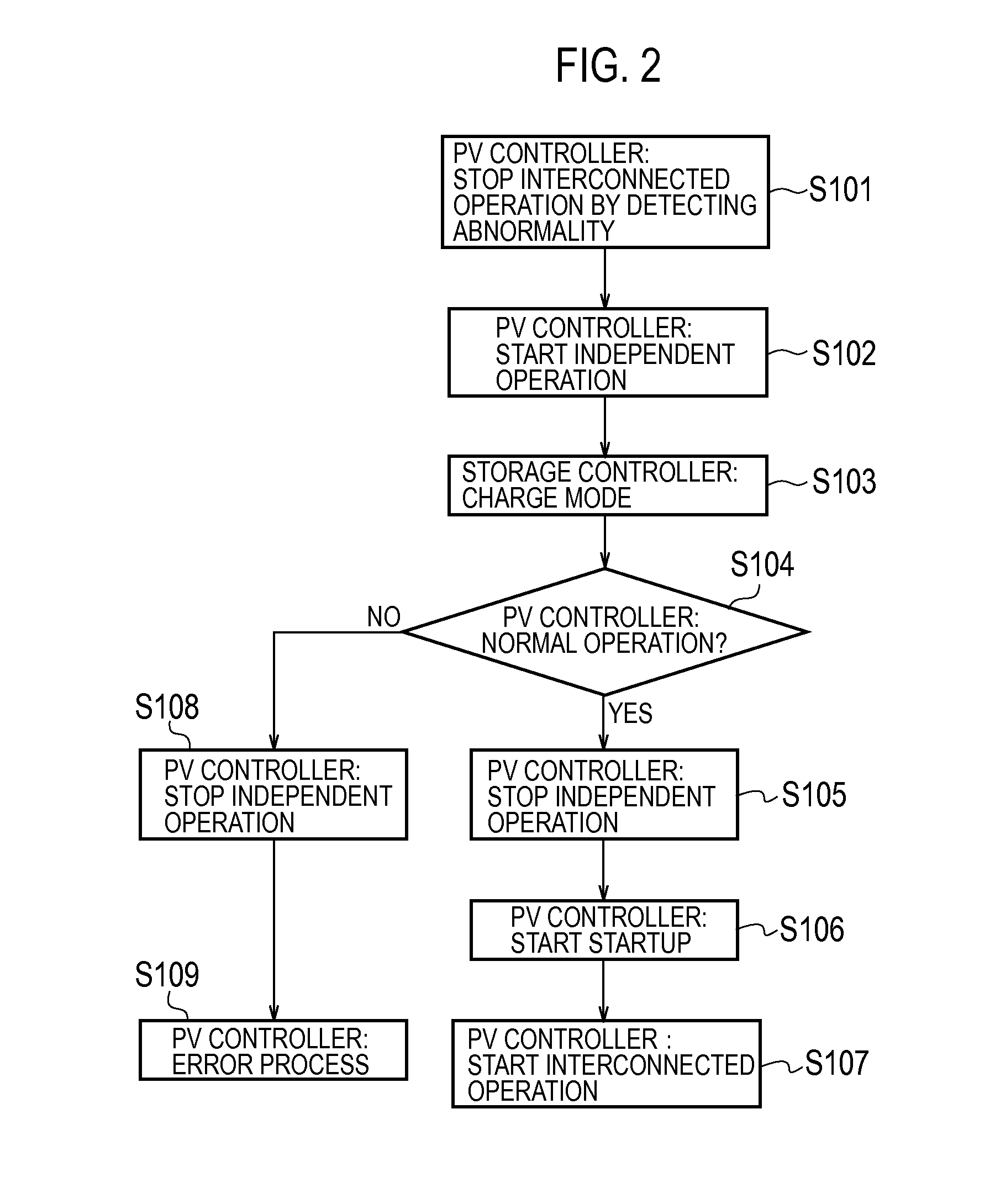
[0070]FIG. 3 is a flowchart of the fault diagnosis method according to the present embodiment. In the present flow, since each of steps other than steps S203 to S205 and S208 is similar to that in the first embodiment, steps S203 to S205 and S208 will be described.

[0071]As shown in FIG. 3, in step S203, when detecting that the AC power is supplied via the PV independent output line PL4, the storage controller 253 starts a charge mode for charging the storage battery 200. In the charge mode, the storage controller 253 may change a charge amount of the storage battery 200. When the charge amount of the storage battery 200 is changed, the output voltage value of the PV PCS 150 ...

third embodiment

[0075]Hereinafter, a third embodiment will be described on a difference from the first embodiment and the second embodiment. FIG. 4 is a block diagram of the power control system according to the present embodiment.

[0076]As shown in FIG. 4, the power control system according to the present embodiment is different from those of the first embodiment and the second embodiment in terms of having an HEMS (Home Energy Management System) 600. The HEMS 600 is to perform power management in a consumer. The HEMS 600 has a function of controlling each equipment in the consumer by transmitting various types of control commands to the PV PCS 150, the storage PCS 250, and the load 400, and a function of collecting various types of measurement values to monitor and display a state of the each device in the consumer. In the present embodiment, the HEMS 600 corresponds to the controller that controls the PV PCS 150 (the grid interconnection apparatus).

[0077]The HEMS 600 includes a HEMS controller 61...


PUM


Abstract

A fault diagnosis method of diagnosing a fault related to a PV PCS 150, configured to perform an interconnected operation in which a PV 100 is interconnected to a grid 10: supplies power from independent operation output of the PV PCS 150 to a storage PCS 250 by an independent operation that does not interconnect the PV 100 to the grid 10 after the grid interconnection apparatus stops the interconnected operation by detecting abnormality; measures an output power state of the PV 100 and / or the PV PCS 150 when power is supplied to the storage PCS 250; and determines that the fault occurs and performs an error process for notification to a user when the measured output power state does not satisfy a predetermined condition.

Description

TECHNICAL FIELD[0001]The present invention relates to a fault diagnosis method of diagnosing a fault related to a grid interconnection apparatus to which output power of a photovoltaic cell is input, the grid interconnection apparatus, and a controller.BACKGROUND ART[0002]In recent years, a photovoltaic cell that receives sunlight to generate power is becoming widely used among power consumers. Along with the wide use of the photovoltaic cell, a grid interconnection apparatus (so-called power conditioner) that interconnects the photovoltaic cell to a commercial power grid (hereinafter, “grid”) to supply power to a load is also becoming widely used.[0003]The grid interconnection apparatus has a grid interconnection relay for performing off-line of the photovoltaic cell from the grid (see Patent Literature 1, for example).CITATION LISTPatent Literature[0004]Japanese Patent Publication No. 2000-350468SUMMARY OF THE INVENTION[0005]The grid interconnection apparatus is configured to, whe...

Claims


Application Information

Patent Timeline
Patent Type & Authority Applications(United States)
IPC IPC(8): H02J3/00G01R31/28
CPCG01R31/28H02J3/00H02J7/35H02J2300/24H02J3/381Y02E10/56
Inventor KUSUNOSE, TOMONARI
Owner KYOCERA CORP
Why Eureka
Try Eureka