Perforated, Layered Wound Treatment Material

a wound treatment material and perforated technology, applied in the field of wound care and wound treatment, can solve the problems of damage to newly formed healing tissue, inability to easily remove the filling material, and tissue cells tending to grow into the used filling or sponge material,

Active Publication Date: 2014-06-12
MEDSKIN SOLUTIONS DR SUWELACK AG
View PDF10 Cites 34 Cited by
  • Summary
  • Abstract
  • Description
  • Claims
  • Application Information

AI Technical Summary

Problems solved by technology

In this case, however, tissue cells tend to grow into the used filling or sponge materials.
As a result, the filling material cannot easily be removed from the wound during dressing changes or after completion of the therapy, but often has to be removed surgically, This can damage the newly formed healing tissue, in the worst case, the newly formed tissue is removed again by the surgery, both of which being generally detrimental to the progress of wound healing.
Moreover, such an additional surgical procedure represents a significant effort, which is connected with unnecessary pain for the patient and a treatment delay.
In addition, the tissue newly formed under a conventional vacuum therapy often does not exhibit a high rigidity, is cosmetically inferior and therefore the healed site tends to reopen and needs to be treated gently.
This represents a significant impairment of quality of life of the patients.
Although collagen in granular or particulate form or as a dispersed mass can easily be sprin

Method used


Image

  • Perforated, Layered Wound Treatment Material
  • Perforated, Layered Wound Treatment Material
  • Perforated, Layered Wound Treatment Material

Examples


example 1

Embodiments

[0145]

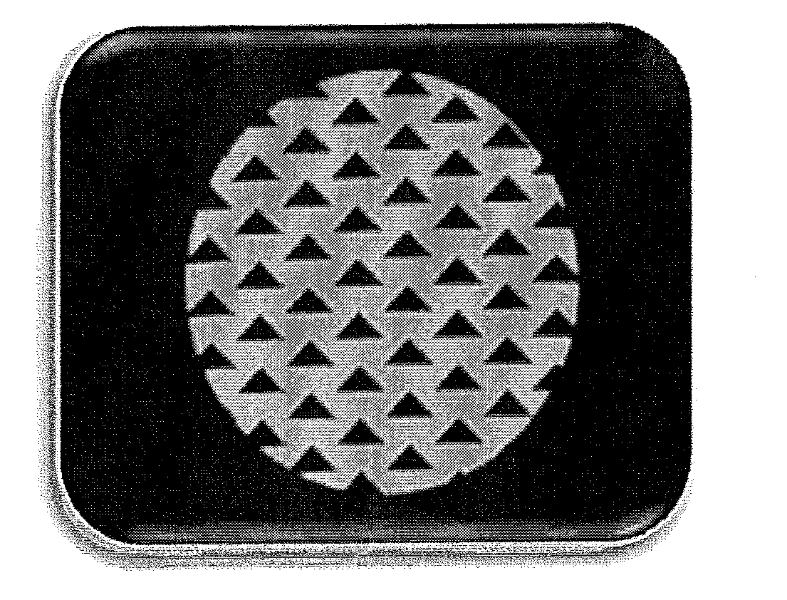
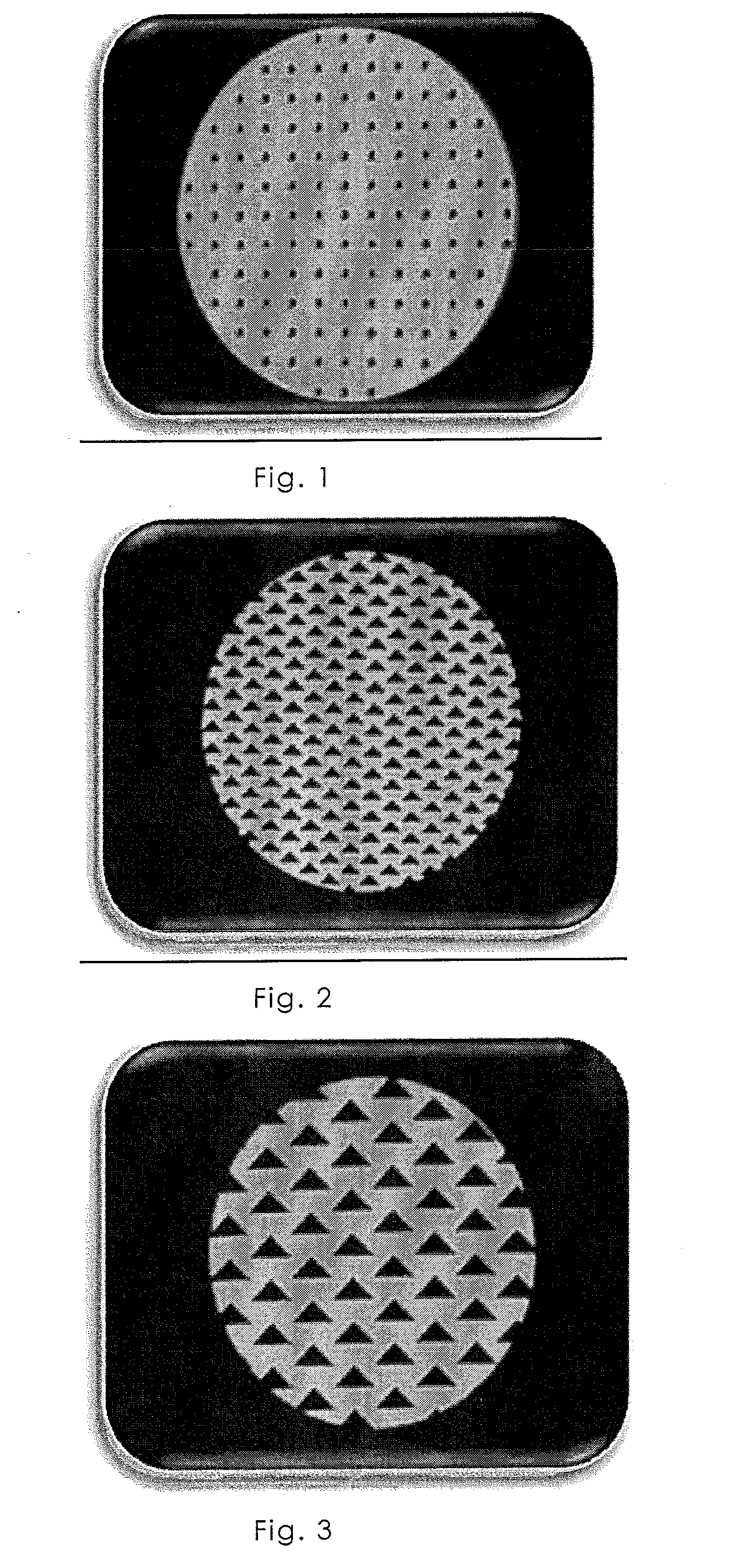
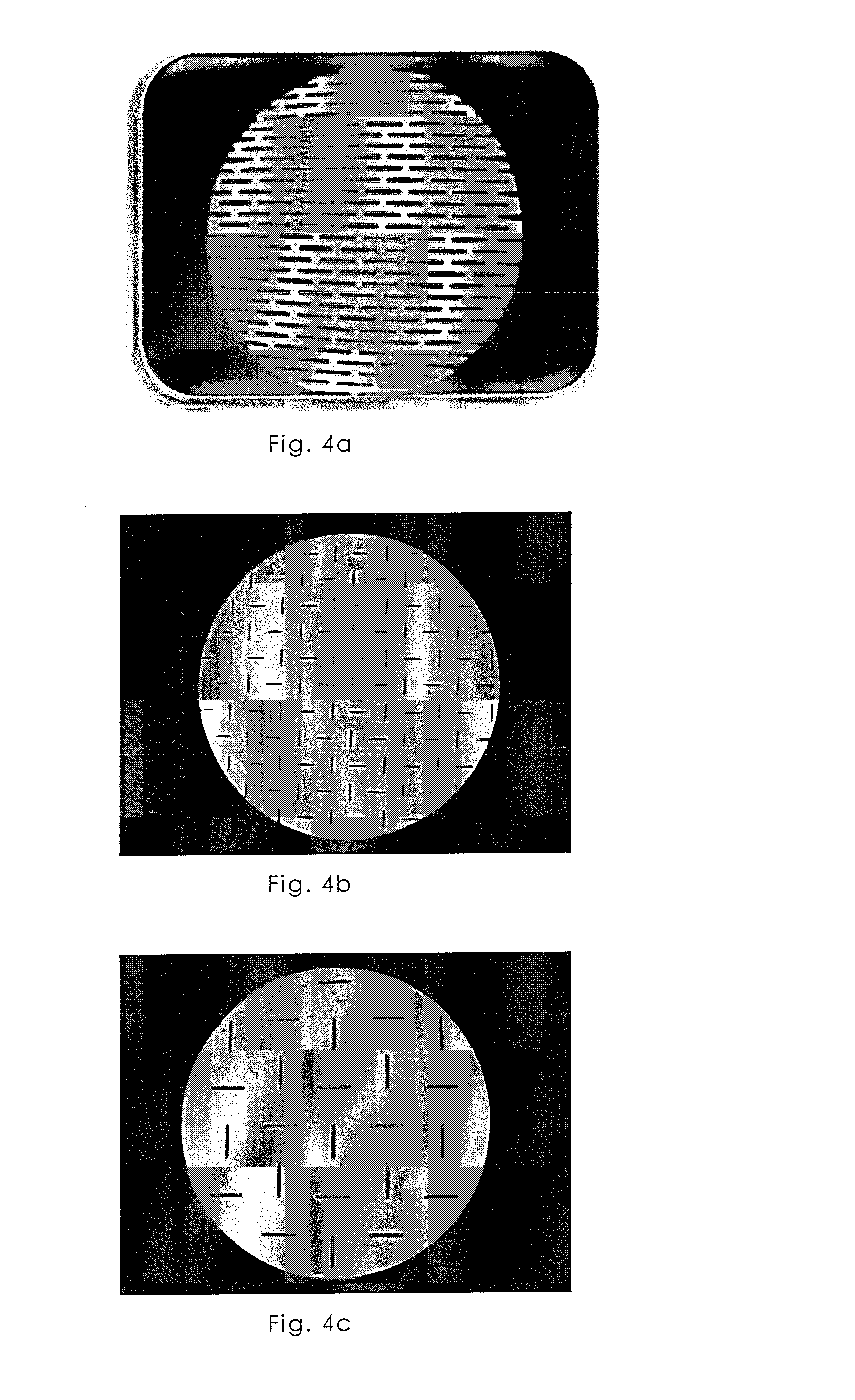
NumberThickness ofTotalConnectingNo.Biomatrixof layersthe layersthicknessmeansPerforation 1acollagen*12mm2 mm—round,Ø 3 mm,(FIG. 1; 13) 1bcollagen*14mm4 mm—round,Ø 2 mm 1ccollagen*16mm6 mm—round,Ø 2 mm 1dcollagen*2each 1mm2 mm—round,epoxide-Ø 2 mmcrosslinked(FIG. 12)(5%) 2collagen*12mm2 mm—triangular,length 4 mm(FIG. 2) 3collagen*12mm2 mm—triangular,length 8 mm(FIG. 3) 4acollagen*12mm2 mm—rectangular,1 × 10 mm(FIG. 4a) 4bcollagen*12mm2 mm—rectangular,0.5 × 5 mm(FIG. 4b) 4ccollagen*12mm2 mm—rectangular,1 × 10 mm(FIG. 4c) 5collagen*2each 2mm4 mmgelatine gluetriangular,4 und 8 mm(FIG. 5) 6acollagen*4each 2mm8 mmgelatine gluerectangular,1 × 10 mm90° offset(FIG. 6a; 14) 6bcollagen*4each 2mm8 mmgelatine glueround,Ø 2 mm(FIG. 15) 7collagen-12mm2 mm—round,alginate-Ø 2 mmmixture* 8collagen-2each 2mm4 mmgelatine glueround,alginate-Ø 2 mmmixture* 9collagen*2each 4mm8 mmchitosan glueround,Ø 2 mm10collagen*2each 4mm8 mmgelatine / round,chitosan glue**Ø 2 mm11collagen*2each 4mm8 mm...

example 2

Investigation in the Wound Simulator

[0148]1. Experimental Setup

[0149]The central component is an aluminum block (dimensions: 150×140×60 mm) with a 2 cm deep circular milled slot with a diameter of 10 cm. In order to control the temperature of the simulator block in a water bath an angle plate of stainless steel was mounted at two opposite sides, they can be bolted to the walls of the water bath that the simulator block is embedded in the water. On the bottom of the block there is a bore for the model liquid supply, at the front of the block the bore for the pressure measurement is located. The aluminum block is heated to 35-37° C. by the water bath to simulate the skin temperature.

[0150]The milled slot is hereinafter referred to as simulator chamber. This is dosed air-tight by means of a thin polymer film which is self-adhesive. For applying pressure a conventional device is in the form of a commercially available so-called T.R.A.C. pad is adhered to the film.

[0151]The vacuum pump f...


PUM

PropertyMeasurementUnit
Thicknessaaaaaaaaaa
Thicknessaaaaaaaaaa
Thicknessaaaaaaaaaa

Abstract

The present invention relates to wound treatment material comprising at least two perforated biomatrix layers interconnected by connecting means, as well as to methods for preparing such wound treatment materials and their use, in particular in the treatment of exuding wounds, and in the vacuum-assisted wound treatment therapy.

Description

[0001]The present invention relates to wound treatment materials comprising at least two perforated biomatrix layers which are interconnected by means of a connecting agent, as well as to methods for producing such wound treatment materials, and to the use thereof, particularly in the treatment of exuding wounds, and in vacuum-assisted wound treatment therapy.INTRODUCTION AND BACKGROUND OF THE INVENTION[0002]In the field of wound care and wound treatment, the application of mechanical and electrical treatment methods has been established in addition to the use of conventional wound dressings. In particular, the negative pressure or vacuum process has been established in order to achieve a more rapid wound healing. This method is known in the medical field by the term Negative Pressure Wound Therapy (NPWT) or vacuum therapy.[0003]In this form of therapy an almost deep wound is equipped with a synthetic or semi-synthetic filling, sponge or foam material, such as a cotton gauze or a po...

Claims


Application Information

Patent Timeline
IPC IPC(8): A61F13/00
CPCA61F13/00042A61F13/00995A61F13/00068A61F13/00063A61L15/28A61L15/325A61L15/425A61F13/0246A61L15/225A61F13/0213A61F13/0226A61F13/0253C08L5/04C08L89/06
Inventor WIELAND, MARTINGRILL, ANTJE
Owner MEDSKIN SOLUTIONS DR SUWELACK AG
Why Eureka
Try Eureka