Light source device and projector
a technology of light source device and projector, which is applied in the direction of picture reproducers using projection devices, lighting and heating apparatus, instruments, etc., can solve the problems of degrading color reproducibility and affecting the quality of image formation, and achieves high color reproducibility and quality
- Summary
- Abstract
- Description
- Claims
- Application Information
AI Technical Summary
Benefits of technology
Problems solved by technology
Method used
Image

Examples
first embodiment
[0032]Hereinafter, a first embodiment of the invention will be explained in detail with reference to the accompanying drawings.
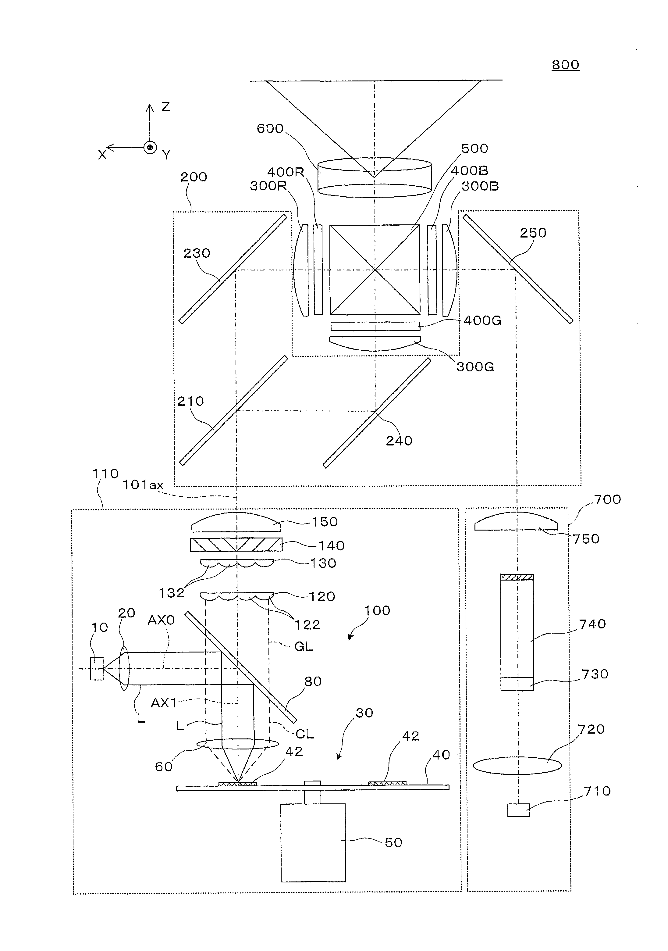
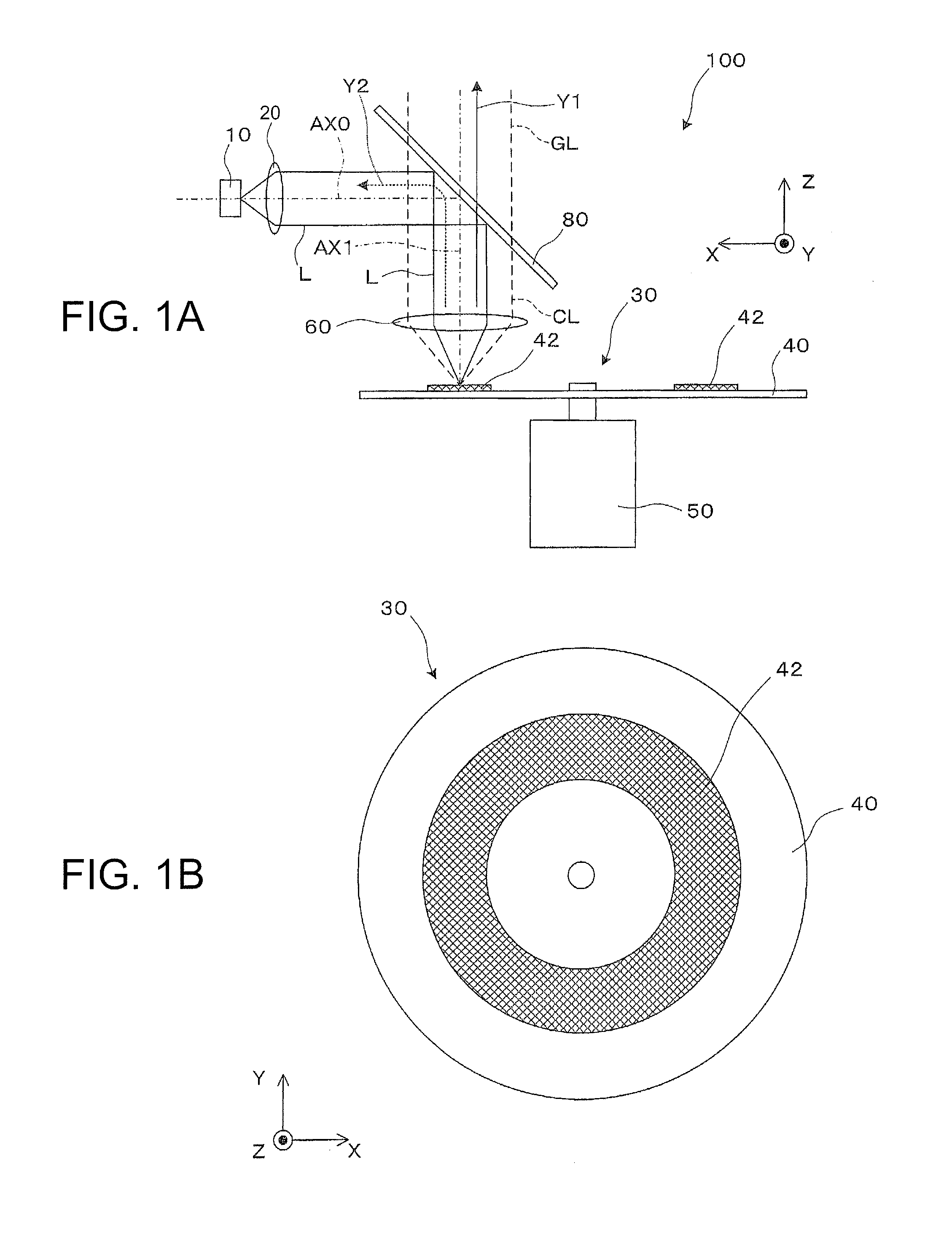
[0033]The light source device 100 shown in FIG. 1A is provided with a phosphor 42 as a wavelength conversion element, a light source 10, a collimating lens 20 as a collimating optical system, a rotary fluorescent plate 30 as a rotating plate for rotatably holding the wavelength conversion element, an electric motor 50, a pickup lens 60, which is a light collection optical system and at the same time functions a collimating optical system, and a wavelength separation element 80. It should be noted that as shown in FIG. 1B, the rotary fluorescent plate 30 has a disk-like shape.
[0034]The light source 10 is a laser source for emitting a blue laser beam L as a first light. The laser beam L has a light emission intensity peak at, for example, about 455 nm, and a wavelength band of 430 through 470 nm as a principal component. The phosphor 42 converts the first ligh...
second embodiment
[0075]Hereinafter, a light source device according to a second embodiment will be explained. It should be noted that the light source device according to the present embodiment is a modified example of the light source device 100 according to the first embodiment, and is roughly the same as the light source device 100 except the structure of apart including the light source through the anterior stage of the wavelength separation element, and therefore, the explanation of the overall device will be omitted.
[0076]As shown in FIG. 6, the light source device 102 according to the present embodiment includes a light source 12 composed of a group of light sources, a collimating lens array 22a for roughly collimating the light from the light source 12, an afocal system 22b for regulating the beam cross-section of the light, and a lens array integrator 22c to thereby evenly illuminate the phosphor 42 with Kohler illumination.
[0077]The light source 12 is obtained by arranging a plurality of s...
third embodiment
[0100]Hereinafter, a light source device according to a third embodiment will be explained. It should be noted that the light source device according to the present embodiment is a modified example of the light source device 100 according to the first embodiment, and is roughly the same as the light source device 100 except the point that the structure of a light transmissive wavelength conversion element is provided, and therefore, the explanation of the overall device will be omitted.
[0101]As shown in FIG. 8A, a light source device 103 according to the present embodiment is provided with a light source 13, a collimating lens 23 as a collimating optical system, a light collection optical system 60a, a rotary fluorescent plate 33 as a rotating plate for rotatably holding the phosphor 42 as the wavelength conversion element, the electric motor 50, a pickup lens 60b as a collimating optical system, a first wavelength separation element 83a, and a second wavelength separation element 8...
PUM
 Abstract
Description
Claims
Application Information
 - R&D
- Intellectual Property
- Life Sciences
- Materials
- Tech Scout
- Unparalleled Data Quality
- Higher Quality Content
- 60% Fewer Hallucinations
Browse by: Latest US Patents, China's latest patents, Technical Efficacy Thesaurus, Application Domain, Technology Topic, Popular Technical Reports.
© 2025 PatSnap. All rights reserved.Legal|Privacy policy|Modern Slavery Act Transparency Statement|Sitemap|About US| Contact US: help@patsnap.com