Suspension board with circuits and method for manufacturing the same

a suspension board and circuit technology, applied in the field of suspension boards with circuits, can solve problems such as short circuits or disconnections at wiring trace, and achieve the effects of high degree of accuracy, improved flexibility at a specific portion of suspension boards, and control of rigidity of suspension boards

Active Publication Date: 2014-06-26
NITTO DENKO CORP
View PDF2 Cites 12 Cited by
  • Summary
  • Abstract
  • Description
  • Claims
  • Application Information

AI Technical Summary

Benefits of technology

[0097]In the suspension board 1 according to the present embodiment, the thick portion 41a and the thin portion 41b are formed at the base insulating layer 41 on the conductive support substrate 10. Thus, flexibility at a specific portion of the suspension board 1 can be improved, and rigidity of the suspension board 1 can be controlled.
[0098]Further, the write wiring traces W1, W2 and the read wiring traces R1, R2 are formed at the base insulating layer 41 to form an angle of not less than 60° and not more than 90° with a boundary line between the thick portion 41a and the boundary surface 41c. In this case, the exposure light is reflected at the boundary surface 41c in a direction that forms a smaller angle with respect to a direction in which the write wiring traces W1, W2 and the read wiring traces R1, R2 extend. Therefore, the reflected light hardly influences the original pattern of the exposure light. Thus, a disconnection is prevented from occurring at the write wiring traces W1, W2 and the read wiring traces R1, R2 that are formed using the photolithographic technique.
[0099]As a result, the posture angle of the suspension board 1 can be adjusted with a high degree of accuracy while reliability of the write wiring traces W1, W2 and the read wiring traces R1, R2 is ensured.
[0100]Further, when the thick portion 41a and thin portion 41b are formed such that the boundary surface 41c forms an angle of 90° with the upper surface of the thin portion 41b of the base insulating layer 41, a process of forming the thick portion 41a and the thin portion 41b at the base insulating layer 41 becomes extremely complicated although the reflected light at the boundary surface 41c is reduced. Further, stress is easily concentrated in the vicinity of the boundary line between the thin portion 41b and the boundary surface 41c at the time of bending.
[0101]In contrast, because the configuration of the present invention causes the reflected light at the boundary surface 41c to hardly influence the original pattern of the exposure light, even in a case in which the boundary surface 41c is inclined with respect to the upper surface of the thin portion 41b, a deficiency due to the reflected light is prevented from occurring at the write wiring traces W1, W2 and the read wiring traces R1, R2 that are formed using the photolithographic technique. Therefore, the boundary surface 41c is inclined with respect to the upper surface of the thin portion 41b, whereby the thick portion 41a and the thin portion 41b can be easily formed at the base insulating layer 41, and concentration of stress applied in the vicinity of the boundary line between the boundary surface 41c and the thin portion 41b can be retrieved.
[0102]While the resist film 14 has negative photosensitivity in the above-mentioned embodiment, the invention is not limited to this. The resist film 14 may have positive photosensitivity.

Problems solved by technology

However, if a wiring trace is formed on the base insulating layer having inconstant thicknesses, a deficiency such as a disconnection or a short-circuit may occur at the wiring trace.

Method used


Image

  • Suspension board with circuits and method for manufacturing the same
  • Suspension board with circuits and method for manufacturing the same
  • Suspension board with circuits and method for manufacturing the same

Examples


first modified example

(4) FIRST MODIFIED EXAMPLE

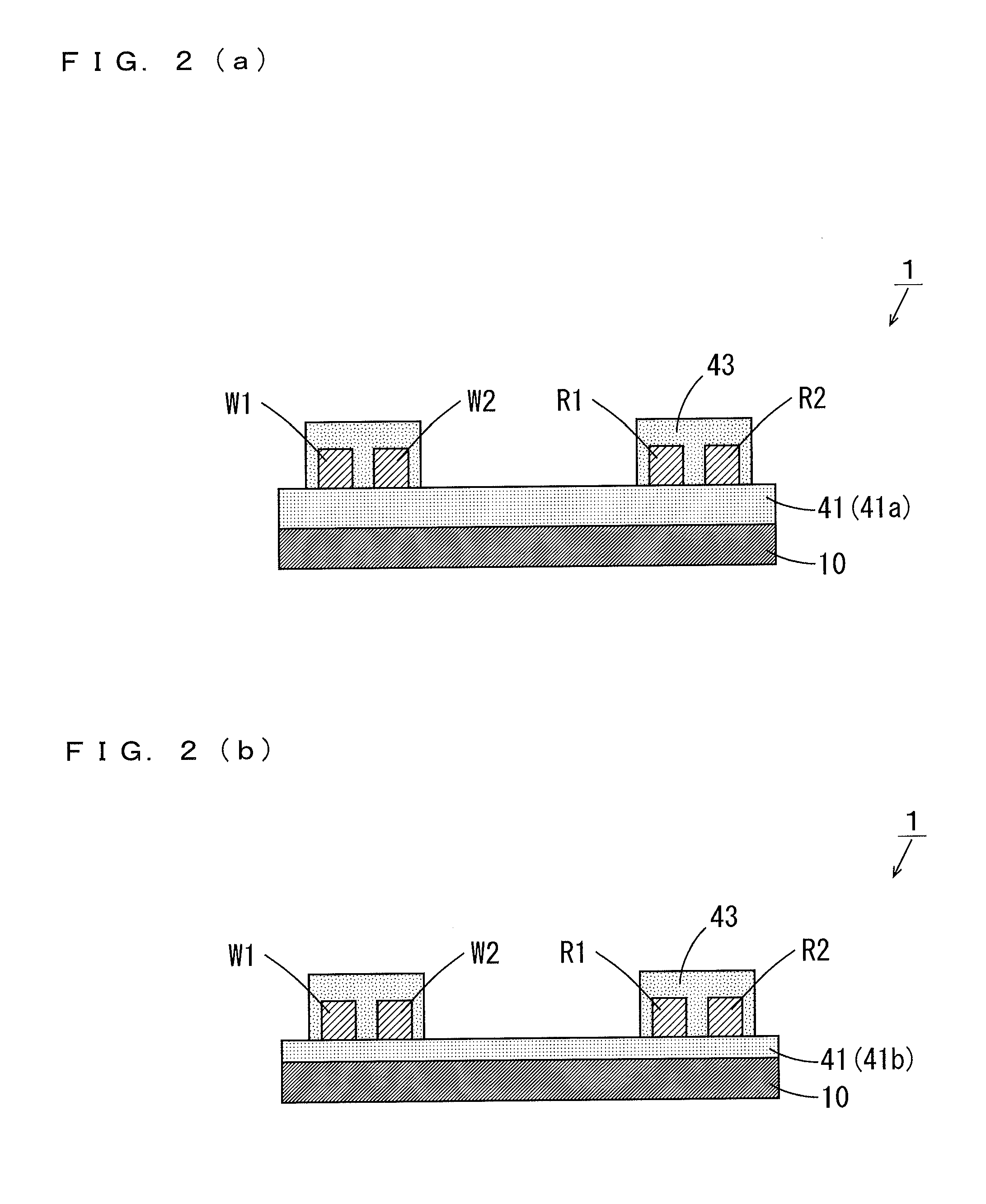
[0089]While the photosensitive polyimide resin precursor 41p on the support substrate 10 is irradiated with ultraviolet rays through a mask having a predetermined gray scale such that the base insulating layer 41 that includes the thick portion 41a and the thin portion 41b is formed on the support substrate 10 in the above-mentioned embodiment, the invention is not limited to this. The base insulating layer 41 that includes the thick portion 41a and the thin portion 41b may be formed using another method as the below-mentioned example.

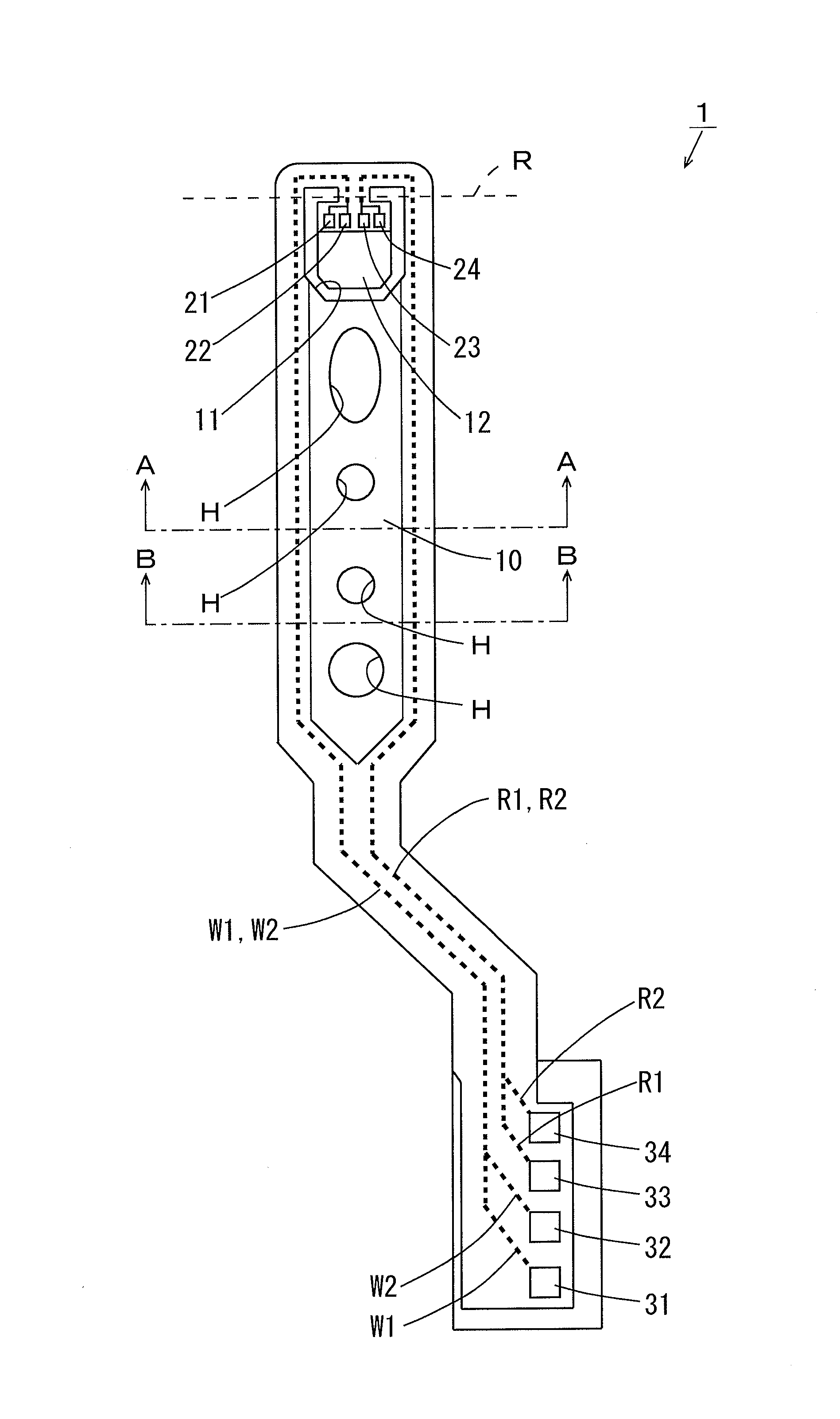
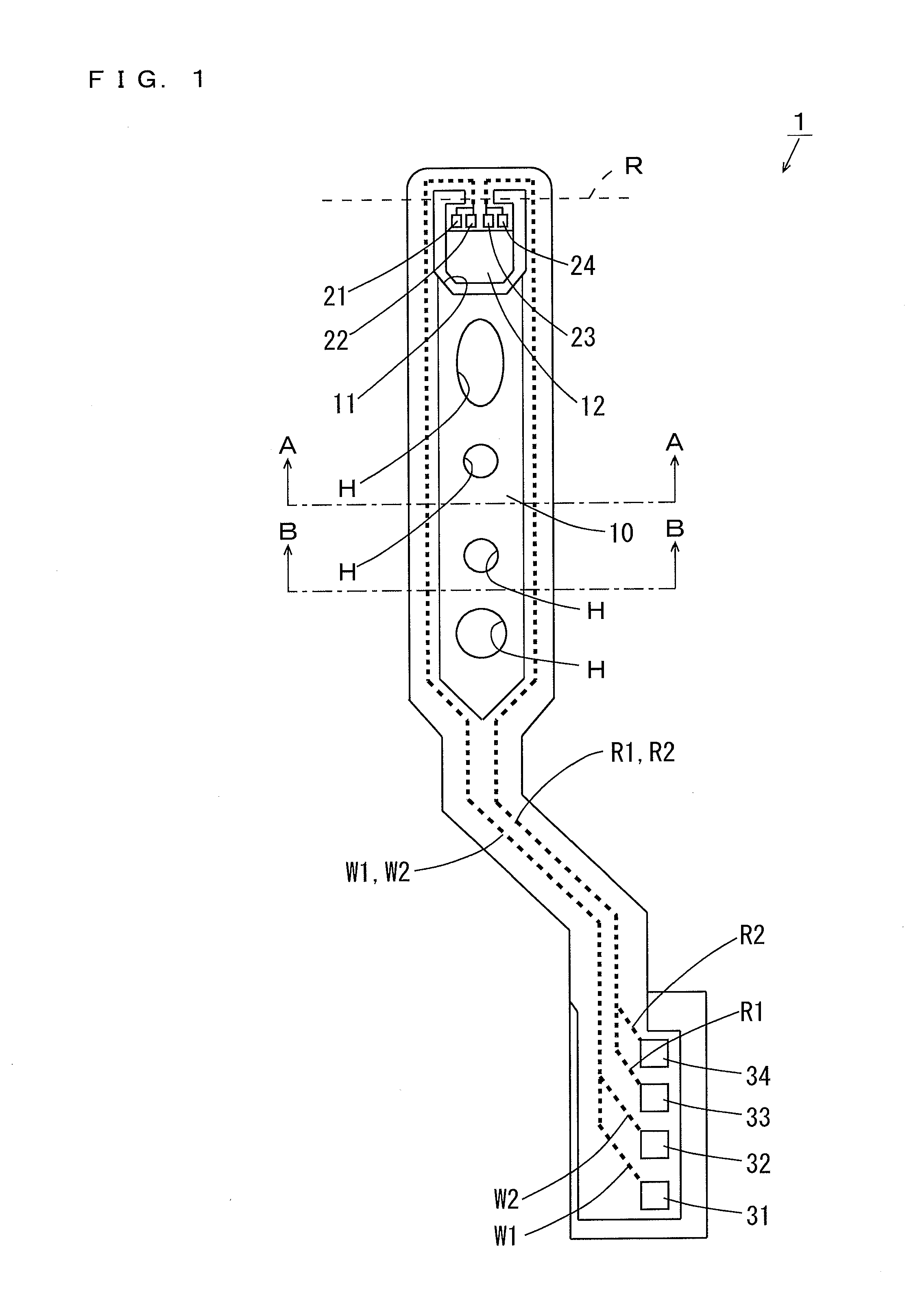
[0090]FIG. 14 is a cross sectional view of the support substrate 10 and the base insulating layer 41 of the suspension board 1 according to the first modified example. The upper diagram in FIG. 14 corresponds to a cross sectional view taken along the line A-A of the suspension board 1 of FIG. 1, and the lower diagram in FIG. 14 corresponds to a cross sectional view taken along the line B-B of the suspension board 1 of FIG. 1.

[...

second modified example

(5) SECOND MODIFIED EXAMPLE

[0094]In the above-mentioned embodiment, the plurality of thin portions 41 b are provided at the base insulating layer 41 such that the thick portion 41a and the thin portion 41b are alternately arranged. In this case, flexibility, at a specific portion in a direction in which the write wiring traces W1, W2 and the read wiring traces R1, R2 of the suspension board 1 extend, can be improved, and rigidity of the suspension board 1 can be controlled. Thus, a posture angle of the suspension board 1 can be adjusted with a high degree of accuracy in a direction in which the write wiring traces W1, W2 and the read wiring traces R1, R2 extend.

[0095]Instead, as described in the below-mentioned example, the one thin portion 41b may be provided at the base insulating layer 41. FIG. 15 is a schematic perspective view of part of the suspension board 1 according to the second modified example. Similarly to FIG. 3, the cover insulating layer 43 is not shown in FIG. 15. A...


PUM

PropertyMeasurementUnit
angleaaaaaaaaaa
angleaaaaaaaaaa
angleaaaaaaaaaa

Abstract

A thick portion having a first thickness and a thin portion having a second thickness on a base insulating layer are formed on a conductive support substrate. The second thickness is smaller than the first thickness. A boundary surface is formed between an upper surface of the thick portion and an upper surface of the thin portion. A boundary line between the upper surface of the thick portion and the boundary surface extends in a first direction. Write wiring traces and read wiring traces are formed to extend on the thick portion and the thin portion of the base insulating layer. The lateral sides of the write wiring traces and the read wiring traces extend in a second direction that intersects with the first direction, and the second direction forms an angle of not less than 60 degrees and not more than 90 degrees with the first direction.

Description

BACKGROUND OF THE INVENTION[0001]1. Field of the Invention[0002]The present invention relates to a suspension board with circuits and a method for manufacturing the suspension board with circuits.[0003]2. Description of Related Art[0004]Actuators are used in drives such as hard disc drives. Such an actuator includes an arm provided rotatably around a rotation shaft, and a suspension board for a magnetic head that is attached to the arm. The suspension board with circuits is a printed circuit board for positioning the magnetic head at a desired track of a magnetic disc.[0005]JP 2012-9111 A describes a flexure that includes a metal substrate for supporting a slider, a base insulating layer formed on the metal substrate, and a wiring formed on the base insulating layer. The wiring is connected to the slider. Signals of recording and reproduction are transmitted to the slider through the wiring.BRIEF SUMMARY OF THE INVENTION[0006]A clearance is formed at a portion of the metal substrate...

Claims


Application Information

Patent Timeline
Patent Type & Authority Applications(United States)
IPC IPC(8): G11B5/48H05K3/10
CPCH05K1/0278H05K1/056H05K3/108H05K3/28H05K2201/0154H05K2201/0191G11B5/486Y10T29/49162G11B5/4853
Inventor SHIRAFUJI, YOUHEI
Owner NITTO DENKO CORP
Why Eureka
Try Eureka