Raw material gas supply apparatus for semiconductor manufacturing equipment

a gas supply apparatus and semiconductor technology, applied in mechanical devices, valves, transportation and packaging, etc., can solve the problems of difficult to highly accurately control the supply quantity of raw material gas g, many unsolved problems, and high labor intensity, so as to improve the flow rate controllability and accurately control the flow rate of supplied gas. , the effect of stably providing raw material gas

Active Publication Date: 2014-07-10
FUJIKIN INC
View PDF8 Cites 149 Cited by
  • Summary
  • Abstract
  • Description
  • Claims
  • Application Information

AI Technical Summary

Benefits of technology

[0028]The present invention is configured to keep a temperature in the source tank at a set value, and to control the supply pressure of a raw material gas G1, which is steam of a liquid raw material gas introduced from an internal upper space portion of the source tank, by employing the automatic pressure regulating device, and to supply the raw material gas G1 to the process chamber via the throttling unit while keeping the raw material gas pressure in the gas distribution passage on the secondary side of the automatic pressure regulating device at a desired set pressure. As a result, it is possible to supply only the raw material gas G1 while highly accurately controlling the flow rate of the supplied gas without using a carrier gas, which makes it possible to stably supply the raw material gas G1 and to significantly improve the flow rate controllability.
[0029]Furthermore, the distribution passage for the raw material gas G1 is composed of the automatic pressure regulating device, the throttling unit and the supply gas switching valve, which is a simple structure that makes it possible to significantly downsize the raw material gas supply apparatus for semiconductor manufacturing equipment, and that makes it easy to judge a consumed quantity of the liquid raw material gas. In addition, backflow of a different type of gas at the time of switching the supply of a raw material gas is effectively prevented by the orifice employed by preferred embodiments of the invention.
[0030]Moreover, the supply pressure of the raw material gas G1 is kept constant by the automatic pressure regulating device, and a caliber of the throttling unit is appropriately selected, and a temperature regulation of the source tank and the raw material gas G1 is performed, thereby making it possible to control a supply flow rate of the raw material gas G1 with an extremely high accuracy, which makes it possible to give high performance of the so-called “film formation” processes, and significantly improve the quality of semiconductor products.

Problems solved by technology

However, there remain many unsolved problems in the conventional gas supply apparatuses shown in FIG. 4 and FIG. 5.
As a result, there is a problem that it takes a lot of time and effort for managing the concentration of the raw material gas G2′ in the mixed gas G0′, which makes it difficult to highly accurately control the supply quantity of the raw material gas G2′.
Furthermore, in the gas supply apparatus shown in FIG. 4, there are problems listed as follows: (A) because the expensive thermal type mass flow control system 23 is used, it is difficult to reduce the manufacturing cost for raw material vaporizing and supplying apparatuses and, additionally, it is necessary to highly accurately control the carrier gas supply pressure to the thermal type mass flow control system 23, which leads to an increase in the equipment cost for the pressure regulator 22; (B) it is not possible to directly control a flow rate of the mixed gas G0′ by the thermal type mass flow control system 23; (C) because the apparatus adopts the bubbling method, it is difficult to stably supply raw material steam in the case of a solid raw material, or a raw material at low steam pressure, which often makes it unstable to supply a mixed gas to the process chamber; (D) the concentration of the raw material steam G2′ in the mixed gas G0′ significantly fluctuates according to a fluctuation in the raw material liquid level in the source tank, which makes it difficult to control the concentration of the raw material steam G2′; (E) because the carrier gas flow rate on the inlet side and the mixed gas flow rate (total flow rate) on the outlet side are different from each other, highly accurate flow control of the mixed gas flow rate is difficult; and (F) it is not easy to highly accurately control the internal pressure of the source tank and, as a result, it is not easy to regulate a raw material concentration directly relating to the partial pressure of the raw material steam in the mixed gas in the tank, and the like.
Moreover, in the gas supply apparatus in FIG. 5, in addition to the problems of (A) to (F) in the gas supply apparatus in FIG. 4, as listed above, there is a problem that, because the apparatus is configured to control a supply quantity of the raw material gas G0′ by adjusting its opening / closing switching time by use of the opening / closing valve V1 provided in the switching mechanism 34 as a pulse-driven valve, not only is achieving highly accurate flow rate control difficult, but also it takes a lot of time and effort for maintenance and management of the opening / closing valve V1.

Method used


Image

  • Raw material gas supply apparatus for semiconductor manufacturing equipment
  • Raw material gas supply apparatus for semiconductor manufacturing equipment
  • Raw material gas supply apparatus for semiconductor manufacturing equipment

Examples


Embodiment Construction

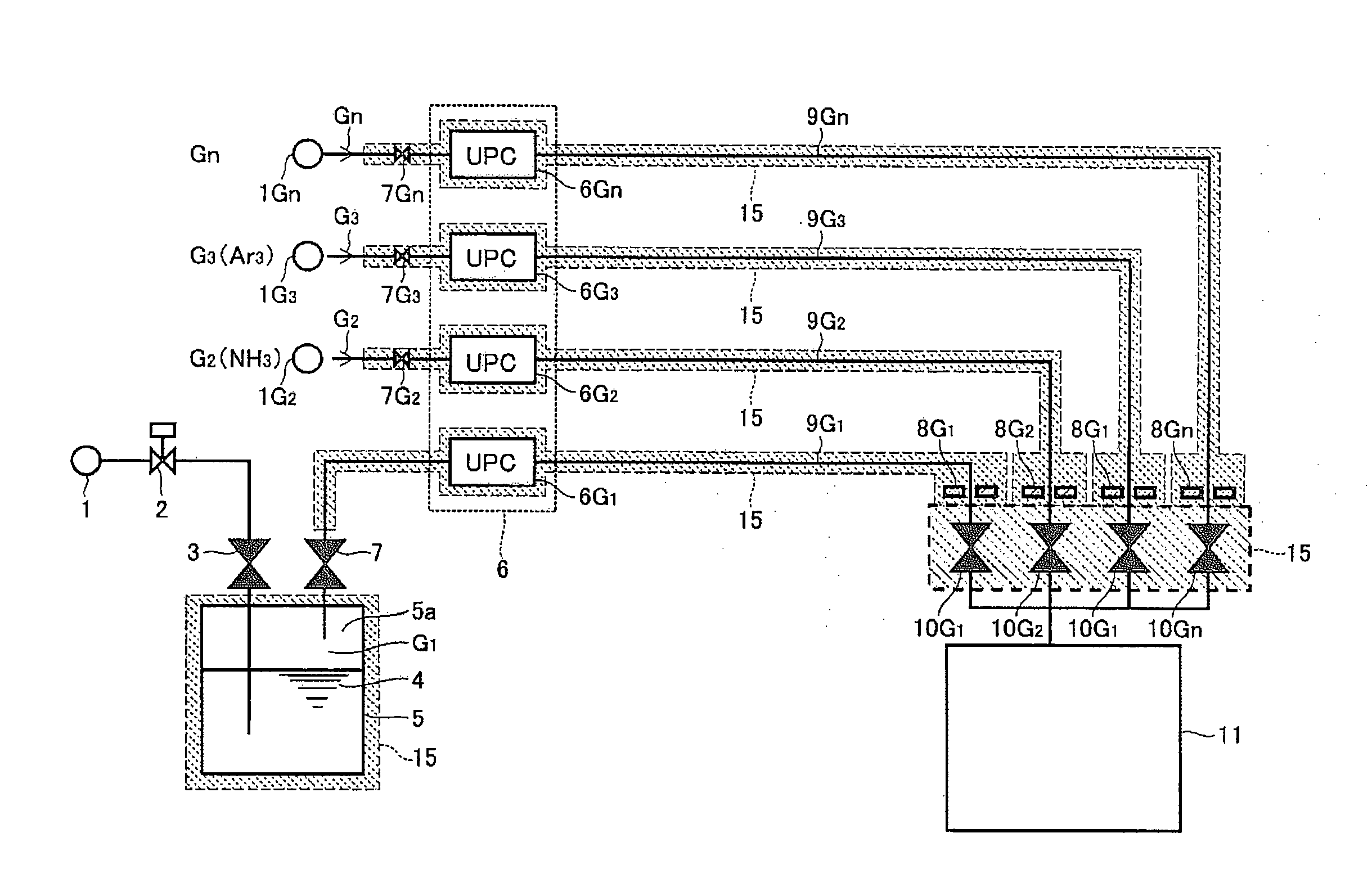
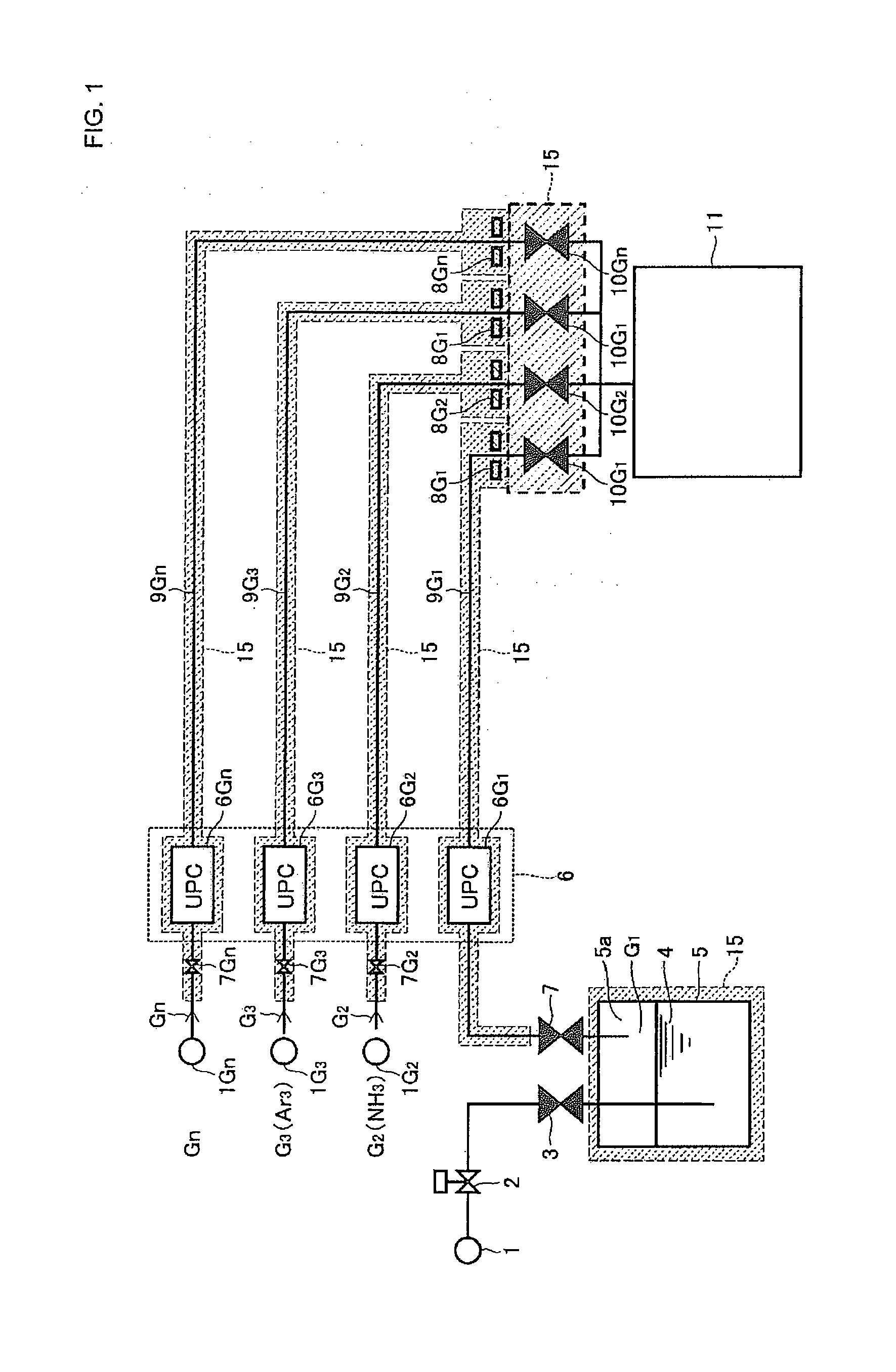
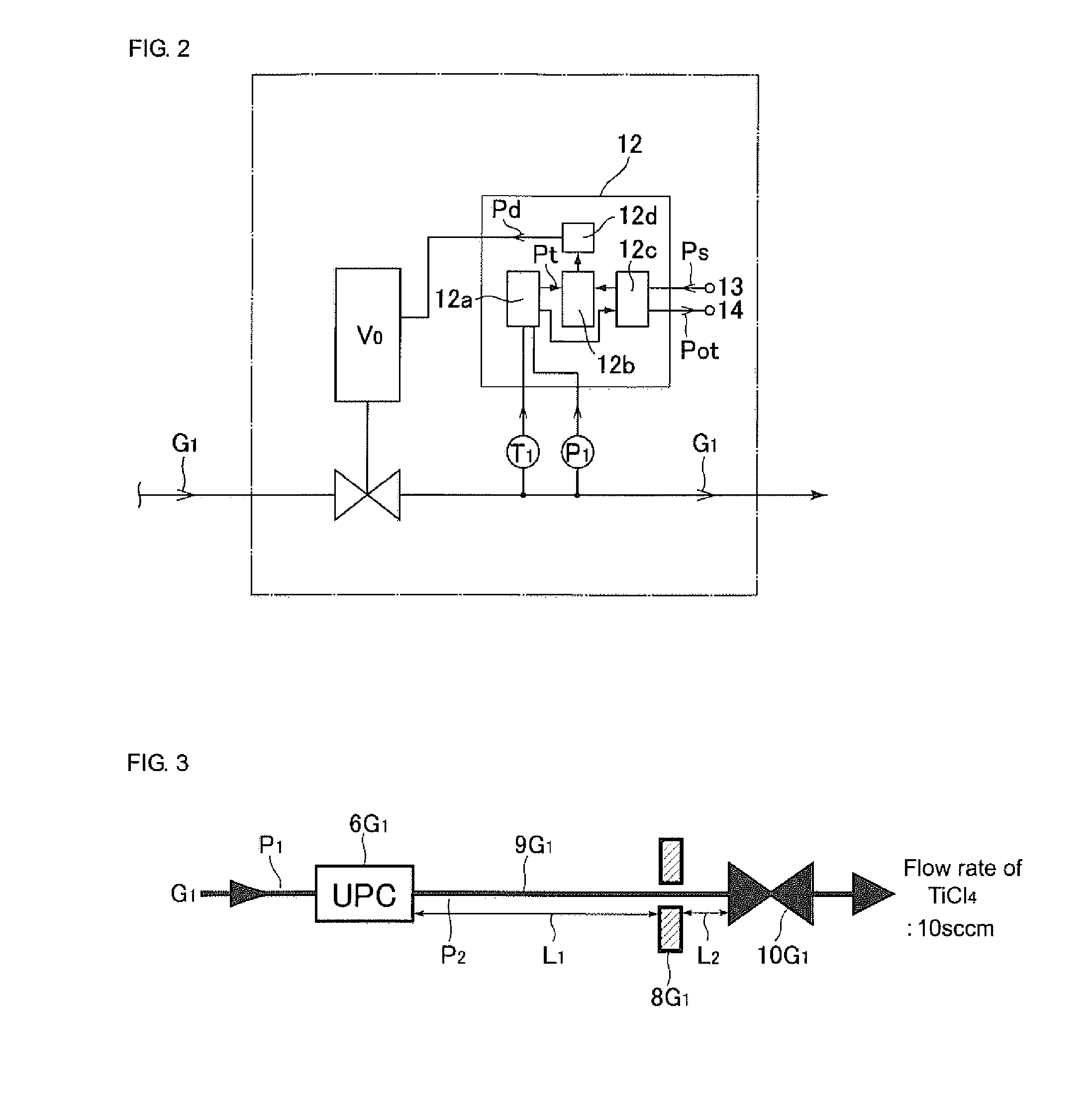
[0036]Hereinafter, an embodiment of the present invention will be described with reference to the drawings. FIG. 1 is a systematic diagram showing a configuration of a raw material gas supply apparatus according to an embodiment of the present invention. The raw material gas supply apparatus is composed of a liquid raw material tank 1, a liquid raw material flow rate meter 2, a liquid raw material supply valve 3, a liquid raw material gas 4, a source tank 5, a raw material gas outlet valve 7, an automatic pressure regulating device 6 that controls internal pressure of distribution passages 9 for the raw material gas supplied to a process chamber 11, a throttling unit 8 (here, orifices 8G1, 8G2, 8G3 and 8Gn are used) that regulates a flow rate of supplying a gas G that is supplied to the process chamber 11, the gas distribution passages 9, supply gas switching valves 10, a constant temperature heating device 15 that heats the gas distribution passages 9, the source tank 5, and the li...


PUM

PropertyMeasurementUnit
temperatureaaaaaaaaaa
pressureaaaaaaaaaa

Abstract

A raw material gas supply apparatus includes a liquid raw material gas supply source, a source tank storing liquid raw material, a gas distribution passage through which raw material gas comprising steam of the liquid raw material is supplied to a process chamber from the source tank, an automatic pressure regulator installed on an upstream side of the gas passage, wherein the automatic pressure regulator keeps supply pressure of the raw material gas at a set value, a supply gas switching valve installed on a downstream side of the gas passage, wherein this valve opens and closes the gas passage, an orifice provided on at least one of an inlet side or outlet side of the valve, wherein the orifice regulates flow rate of the raw material gas, and a constant temperature heating device heats the source tank, the gas passage, the valve and the orifice to a set temperature.

Description

[0001]This is a Continuation-in-Part Application in the United States of International Patent Application No. PCT / JP2012 / 002832 filed Apr. 25, 2012, which claims priority on Japanese Patent Application No. 2011-151375, filed Jul. 8, 2011. The entire disclosures of the above patent applications are hereby incorporated by reference.BACKGROUND OF THE INVENTION[0002]1. Field of the Invention[0003]The present invention relates to an improvement in a gas supply apparatus for semiconductor manufacturing equipment by a so-called “ALD method,” and, in particular, to a raw material gas supply apparatus for semiconductor manufacturing equipment that is capable of rapidly and accurately switching to supply a plurality of processing gases (e.g., raw material gases) while highly accurately controlling the flow rate of those processing gases to the inside of a process chamber.[0004]2. Description of the Related Art[0005]A so-called ALD (Atomic Layer Deposition) method has been widely utilized for ...

Claims


Application Information

Patent Timeline
Patent Type & Authority Applications(United States)
IPC IPC(8): C23C16/448
CPCC23C16/448C23C16/45561C23C16/52Y10T137/86485H01L21/31C23C16/4485
Inventor NAGASE, MASAAKIHIDAKA, ATSUSHIHIRATA, KAORUDOHI, RYOUSUKENISHINO, KOUJIIKEDA, NOBUKAZU
Owner FUJIKIN INC
Why Eureka
Try Eureka