Composite Wafer and Method for Manufacturing the Same

Active Publication Date: 2014-07-10
NGK INSULATORS LTD
View PDF5 Cites 10 Cited by
  • Summary
  • Abstract
  • Description
  • Claims
  • Application Information

AI Technical Summary

Benefits of technology

[0020]According to this method, the composite wafer of the present invention described above can be easily obtained.
[0021]In the method for manufacturing a composite wafer according to the present invention, in step (1), a polycrystalline translucent ceramic is used. Such a translucent ceramic can be obtained, for example, by a method in which a slurry containing ceramic powder, a gelling agent, and a gelling catalyst is poured into a mold and solidified to form a formed body, and then the formed body is released from the mold and sintered in a hydrogen atmosphere. The sintering temperature is preferably set at 1,700° C. to 1,800° C. Thereby, the average crystal grain size can be set to 10 μm or more, and the total light transmittance from the front of the translucent ceramic at a wavelength of 200 to 250 nm can be set to be higher than the total light transmittance from the front at a wavelength of 555 nm. When it is desi

Problems solved by technology

However, GaAs platforms have a drawback in that power consumption cannot be decreased because of current leakage to substrates, and the like.
There

Method used


Image

  • Composite Wafer and Method for Manufacturing the Same
  • Composite Wafer and Method for Manufacturing the Same
  • Composite Wafer and Method for Manufacturing the Same

Examples


Example

Example 1

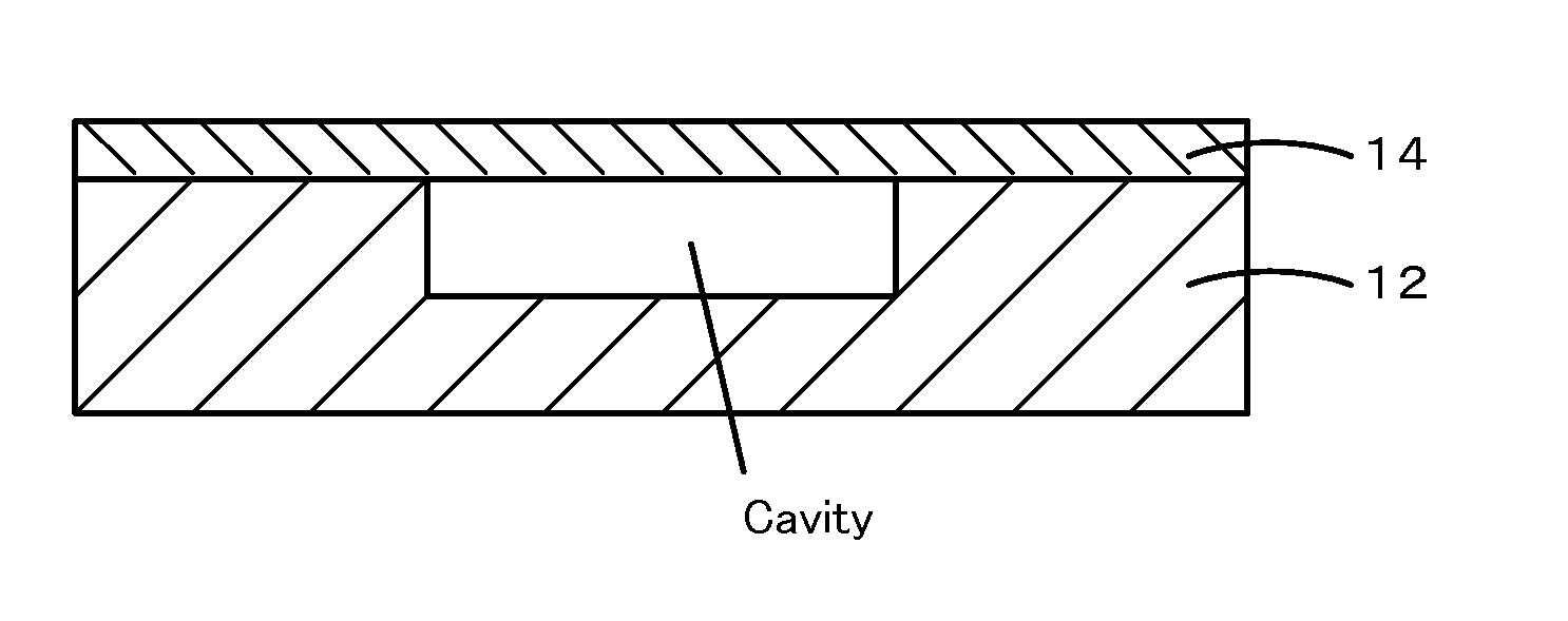
[0046]First of all, a translucent alumina substrate used as a supporting substrate was prepared by the process described below. First, a slurry was prepared in which components shown in Table 1 were mixed. The α-alumina powder used had a purity of 99.99%, a specific surface of 3.5 to 4.5 m2 / g, and an average primary particle size of 0.35 to 0.45 μm.

ComponentsPart by weightRaw materialAl2O3(α-alumina powder)100powderMgO(Magnesia)0.050ZrO2(zirconia)0.040Y2O3(yttria)0.0030Disperse mediumDimethyl glutarate27Ethylene glycol0.3Gelling agentMDI resin4DispersantHigh molecular surface-active agent3CatalystN,N-Dimethylamino hexanol0.1

[0047]The slurry was poured into a mold made of an aluminum alloy at room temperature and then left standing at room temperature for one hour. Next, it was left standing at 40° C. for 30 minutes to cause solidification to proceed and then released from the mold. Furthermore, the solidified slurry was left standing at room temperature and at 90° C., each...

Example

Example 2

[0052]Using the slurry employed for producing the polycrystalline translucent alumina substrate of Example 1, a polycrystalline translucent alumina substrate was produced by the same procedure as that of Example 1 except that firing was performed once at a firing temperature of 1,700° C. The total light transmittance from the front was measured on the resulting polycrystalline translucent alumina substrate without grinding the surface. As shown in FIG. 4, the total light transmittance from the front was less than 70% at the visible light wavelength (measurement wavelength: 555 nm), but was high at 70% or more at a wavelength of 200 to 250 nm. The average grain size of the translucent alumina substrate was 12 μm. The translucent alumina substrate was ground to a thickness of 0.6 mm as in Example 1. The linear transmittance in the visible light range of the substrate was measured to be 30% (measurement wavelength: 555 nm). Furthermore, the tan δ was 10−5, the volume resistivi...

Example

Comparative Example 1

[0053]Using the slurry employed for producing the polycrystalline translucent alumina substrate of Example 1, a polycrystalline translucent alumina substrate was produced by the same procedure as that of Example 1 except that firing was performed once in a hydrogen atmosphere with the firing temperature being changed to 1,500° C. The total light transmittance from the front was measured on the resulting polycrystalline translucent alumina substrate without grinding the surface. The total light transmittance from the front was 25% at the visible light wavelength (measurement wavelength: 555 nm), but was lower than that at a wavelength of 200 to 250 nm. The total light transmittance from the front at 200 nm to 2 μm of the translucent alumina substrate was 40% or less, and the average grain size was 5 μm. The translucent alumina substrate was ground to a thickness of 0.6 mm as in Example 1. The linear transmittance in the visible light range of the substrate was m...


PUM


Abstract

A composite wafer 10 includes a supporting substrate 12 and a semiconductor substrate 14 which are bonded to each other by direct bonding. The supporting substrate 12 is a translucent alumina substrate with an alumina purity of 99% or more. The linear transmittance of the supporting substrate 12 at the visible light range is 40% or less. Furthermore, the total light transmittance from the front at a wavelength of 200 to 250 nm of the supporting substrate 12 is 60% or more. The average crystal grain size of the supporting substrate 12 is 10 to μm. The semiconductor substrate 14 is a single crystal silicon substrate. Such a composite wafer 10 has insulation performance and thermal conduction comparable to those of a SOS wafer, can be manufactured at low cost, and can be easily made to have a large diameter.

Description

TECHNICAL FIELD [0001]The present invention relates to a composite wafer and a method for manufacturing the same.BACKGROUND ART [0002]As antenna switches used for mobile phones, in order to fulfill the multi-mode, multi-band demands, pHEMT switches using GaAs have been used from the viewpoint of linearity and strain suppression. However, GaAs platforms have a drawback in that power consumption cannot be decreased because of current leakage to substrates, and the like. Furthermore, a switching device needs to separately have decoder circuits made of Si provided outside thereof. Therefore, when a GaAs platform is used, it is not possible to integrate the circuits. Consequently, there is a limit to the reduction in size and cost.[0003]In recent years, in order to solve the problem described above, there has been provided a SOI (Silicon on Insulator) technique (for example, refer to Patent Literature 1). A SOI wafer is known in which a SiO2 layer is formed on the upper portion of a Si l...

Claims


Application Information

Patent Timeline
IPC IPC(8): H01L29/06H01L21/762
CPCH01L21/76251H01L29/06H01L21/76254H01L21/02002H01L21/2007H01L21/762
Inventor IWASAKI, YASUNORIIDE, AKIYOSHIHORI, YUJITAI, TOMOYOSHIMIYAZAWA, SUGIO
Owner NGK INSULATORS LTD
Why Eureka
Try Eureka