
Silicon-germanium heterojunction tunnel field effect transistor and preparation method thereof

Active Publication Date: 2014-07-17
SHANGHAI INST OF MICROSYSTEM & INFORMATION TECH CHINESE ACAD OF SCI
View PDF0 Cites 5 Cited by
  • Summary
  • Abstract
  • Description
  • Claims
  • Application Information

AI Technical Summary

Benefits of technology

The present invention describes a new type of transistor that uses a special material called silicon germanium (SiGe) to achieve high performance and low power consumption. This transistor is manufactured using a process that allows for precise control over the amount of SiGe and silicon (Si) in the device, resulting in a high ON-state current and low OFF-state current. The process is simple and compatible with standard semiconductor manufacturing methods, making it suitable for mass production. The SiGe transistor also includes a structure that reduces defects and ensures a high-quality product.

Problems solved by technology

However, with the development of the microelectronic technology, it becomes more and more difficult to reduce the size of a conventional silicon-based Complementary Metal-Oxide-Semiconductor Transistor (CMOS) proportionally.
Moreover, most electronic products manufactured using Metal-Oxide-Semiconductor Field-Effect Transistors (MOSFETs) have the following problems: First, electric leakage increases as the channel of the MOSFET becomes shorter, and power keeps being consumed even in an off state or standby state.
Citing a report from the European Union, IBM points out that 10% of home and office electricity is wasted for the standby state of electronic products.
Secondly, restricted by the physical mechanism, a conventional MOSFET has a large sub-threshold swing.
However, the ON-state current of the silicon-based TFET is small.
For SiGe film with a high Ge content, due to the limit of lattice mismatch (4.2%) between Ge and Si, when the material grows beyond a critical thickness thereof, a lot of defects are incurred, leading to greater electric leakage of devices.
If the film is excessively thin, a device process is difficult to implement.

Method used


Image

  • Silicon-germanium heterojunction tunnel field effect transistor and preparation method thereof
  • Silicon-germanium heterojunction tunnel field effect transistor and preparation method thereof
  • Silicon-germanium heterojunction tunnel field effect transistor and preparation method thereof

Examples


Embodiment Construction

[0027]The implementation manner of the present invention is described in detail below through specific embodiments. Persons skilled in the art can easily learn other advantages and efficacies of the present invention according to the disclosure of the specification. The present invention can also be implemented or applied through other embodiments. Based on different perspectives and applications, modifications or alterations without departing from the spirit of the present invention can be made to the details in the specification.

[0028]It should be noted that, the drawings provided in the embodiment is merely an example for illustrating the basic ideas of the present invention. Therefore, only the components related to the present invention are shown in the drawings, and the drawings are not based on the number, shapes and sizes of components in practical implementations. The forms, number and proportion of the components in practical implementations may be changed randomly, and th...


PUM


Abstract

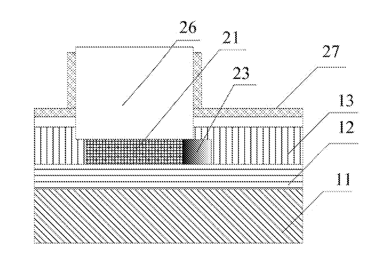
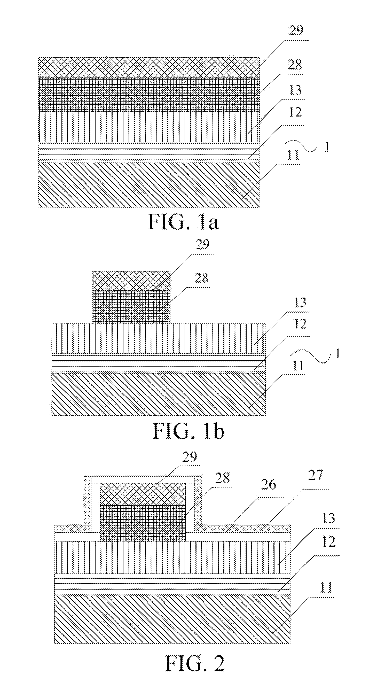
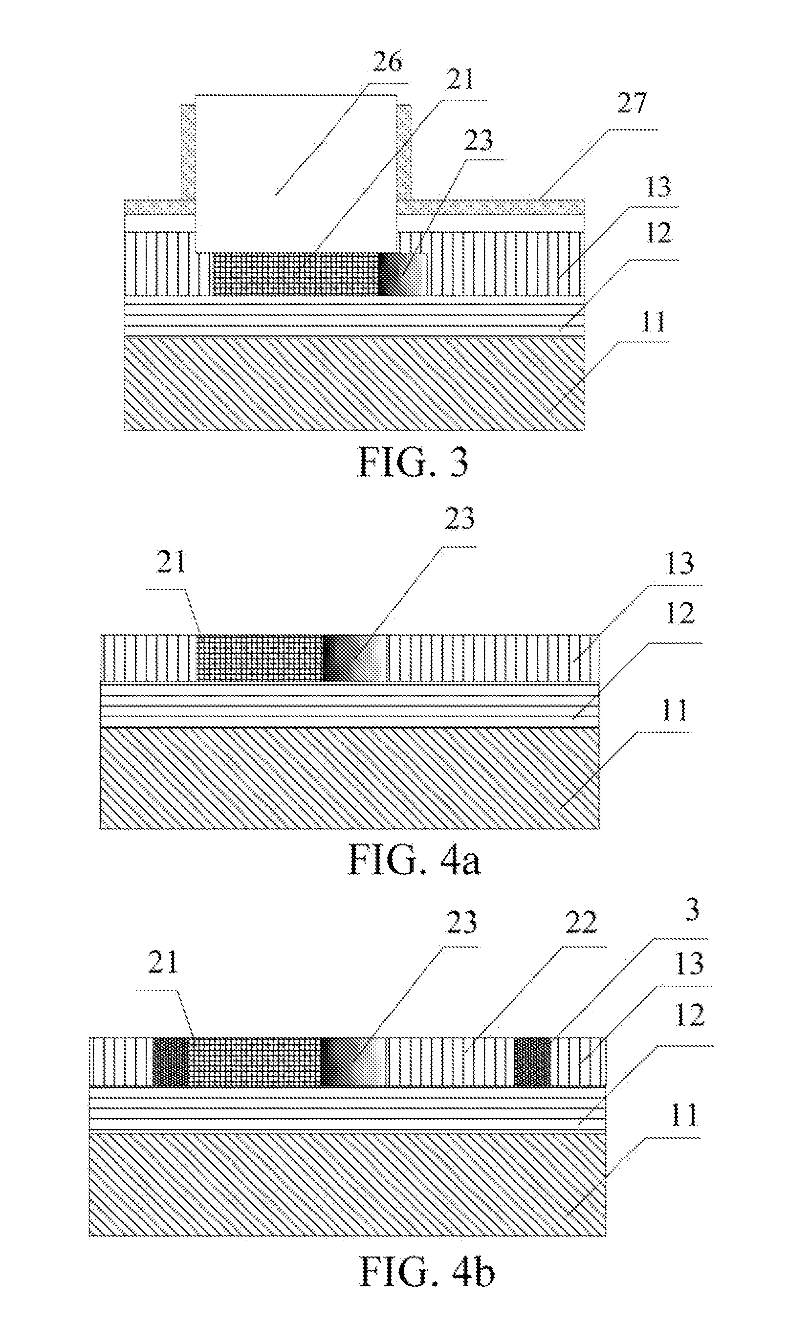
A silicon / germanium (SiGe) heterojunction Tunnel Field Effect Transistor (TFET) and a preparation method thereof are provided, in which a source region of a device is manufactured on a silicon germanium (SiGe) or Ge region, and a drain region of the device is manufactured in a Si region, thereby obtaining a high ON-state current while ensuring a low OFF-state current. Local Ge oxidization and concentration technique is used to implement a Silicon Germanium On Insulator (SGOI) or Germanium On Insulator (GOI) with a high Ge content in some area. In the SGOI or GOI with a high Ge content, the Ge content is controllable from 50% to 100%. In addition, the film thickness is controllable from 5 nm to 20 nm, facilitating the implementation of the device process. During the oxidization and concentration process of the SiGe or Ge and Si, a SiGe heterojunction structure with a gradient Ge content is formed between the SiGe or Ge and Si, thereby eliminating defects. The preparation method according to the present invention has a simple process, which is compatible with the CMOS process and is applicable to mass industrial production.

Description

BACKGROUND OF THE PRESENT INVENTION[0001]1. Field of Invention[0002]The present invention relates to a transistor and a preparation method thereof, and specifically to a silicon (Si)-germanium (Ge) heterojunction Tunnel Field Effect Transistor (TFET) and a preparation method thereof.[0003]2. Description of Related Arts[0004]In recent years, the microelectronic technology centered on silicon integrated circuits develops rapidly. The development of the integrated circuit chip follows Moore's Law, that is, the degree of integration of semiconductor chips doubles every 18 months. In the past, the advancement of the microelectronic technology is based on the continuous optimization of the cost effectiveness of materials and processes. However, with the development of the microelectronic technology, it becomes more and more difficult to reduce the size of a conventional silicon-based Complementary Metal-Oxide-Semiconductor Transistor (CMOS) proportionally. Moreover, most electronic produc...

Claims


Application Information

Patent Timeline
IPC IPC(8): H01L21/02H01L29/66
CPCH01L21/02532H01L21/02617H01L29/66431H01L29/66356H01L29/7391H01L29/165
Inventor BIAN, JIANTAOXUE, ZHONGYINGDI, ZENGFENGZHANG, MIAO
Owner SHANGHAI INST OF MICROSYSTEM & INFORMATION TECH CHINESE ACAD OF SCI
Learn More