
Methods For Reservoir Evaluation Employing Non-Equilibrium Compositional Gradients

Active Publication Date: 2014-07-17
SCHLUMBERGER TECH CORP
View PDF10 Cites 15 Cited by
  • Summary
  • Abstract
  • Description
  • Claims
  • Application Information

AI Technical Summary

Benefits of technology

The patent provides methods for better understanding reservoir fluids, especially when it is hard to determine if the reservoir is divided into compartments or connected but not in a state of balance.

Problems solved by technology

Reservoir compartmentalization can be a significant impediment to efficient reservoir development.
However, impermeable barriers may be so thin that they are not observable by these logs, or barriers observed by these logs may not extend away from the wellbore and therefore may not compartmentalize the reservoir.
However, the presumption that pressure communication implies flow communication has been repeatedly proven to be incorrect.
Continuous pressure gradients are a necessary but insufficient test for reservoir connectivity.
However, forces such as biodegradation and water washing can occur to different extents in different parts of the reservoir, causing two locations in the reservoir to have different fingerprints even if they are connected.
It can be difficult to determine whether the reservoir is compartmentalized or in a state of thermodynamic non-equilibrium, and this determination can be critical to important development decisions.
Most of these mechanisms result in non-equilibrium or non-stationary state conditions acting on reservoir fluids and, often, these non-equilibrium factors dominate over diffusive and convective processes that can drive the fluids towards equilibrium.
In these scenarios, the current modeling methods can be inaccurate and offer limited insight into the real compositional properties of the reservoir fluids.
These limitations make it difficult to determine whether the reservoir is compartmentalized or connected, but in a state of non-equilibrium.

Method used


Image

  • Methods For Reservoir Evaluation Employing Non-Equilibrium Compositional Gradients
  • Methods For Reservoir Evaluation Employing Non-Equilibrium Compositional Gradients
  • Methods For Reservoir Evaluation Employing Non-Equilibrium Compositional Gradients

Examples


Embodiment Construction

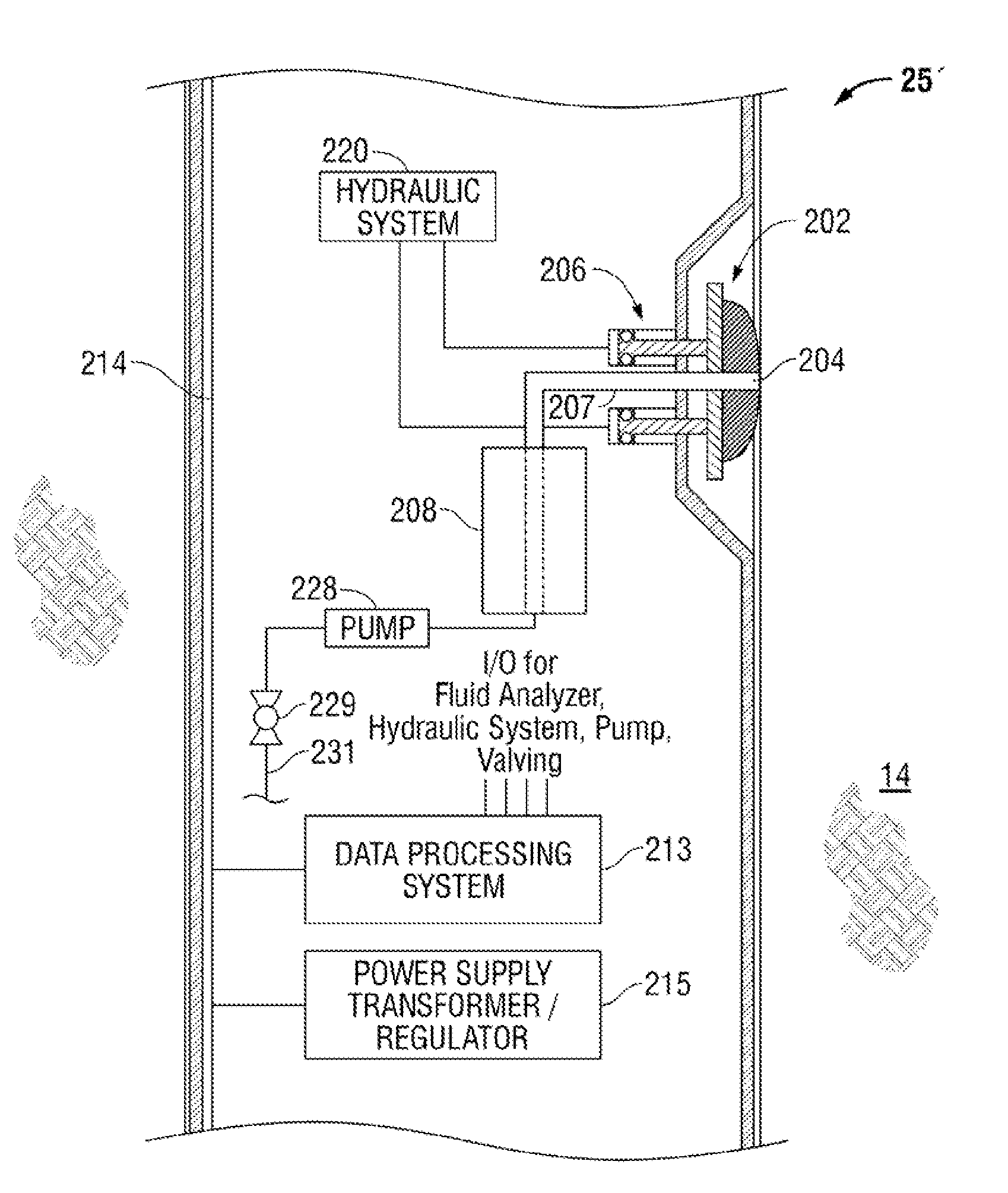
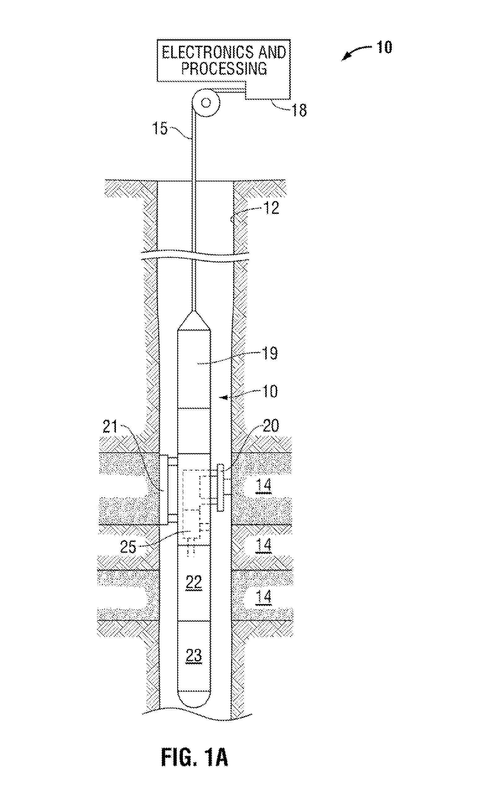
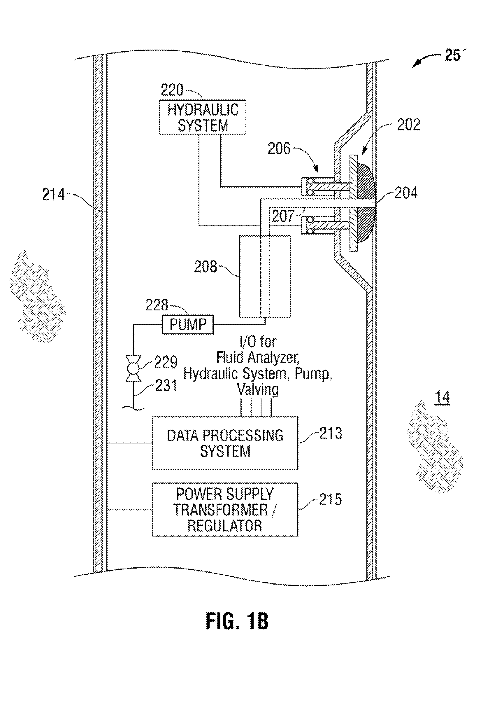
[0026]FIG. 1A illustrates an exemplary tool 10 for petroleum reservoir downhole fluid analysis that can be used as part of a workflow for reservoir analysis in accordance with the present invention. The tool 10 is suspended in the borehole 12 from the lower end of a typical multiconductor cable 15 that is spooled in a usual fashion on a suitable winch on the earth's surface. The cable 15 is electrically coupled to an electrical control system 18 on the earth's surface. The tool 10 includes an elongated body 19 which carries a selectively extendable fluid admitting assembly 20 and a selectively extendable tool anchoring member 21 which are respectively arranged on opposite sides of the tool body 19. The fluid admitting assembly 20 is equipped for selectively sealing off or isolating selected portions of the wall of the borehole 12 such that fluid communication with the adjacent earth formation 14 is established. The fluid admitting assembly 20 and tool 10 include a flowline leading t...


PUM


Abstract

A method for determining reservoir architecture using modeling of a non-equilibrium distribution of at least one analyte in reservoir fluids. The analyte(s) of the analysis preferably has (have) significant compositional variation in the reservoir. For example, the analyte can be a later charging single gas component (such as methane, carbon dioxide, or hydrogen sulfide) in a multi-component fluid system. In this case, the model can assume that the components of the early charge are in a stationary state or in equilibrium, whereas the later charge is in a state of non-equilibrium. The non-equilibrium distribution of the analyte(s) derived from the model is compared to the distribution of the analyte(s) derived from downhole or laboratory fluid analysis of reservoir fluid, and the architecture of the reservoir is determined based upon such comparison.

Description

CROSS-REFERENCE TO RELATED APPLICATIONS[0001]The present invention claims priority from U.S. Provisional Patent Application 61 / 387,066, filed on Sep. 28, 2010, which is incorporated herein by reference in its entirety.BACKGROUND OF THE INVENTION[0002]1. Field of the Invention[0003]The present invention relates to methods for characterizing petroleum fluids extracted from a hydrocarbon-bearing geological formation. The invention has application to reservoir architecture understanding, although it is not limited thereto.[0004]2. Description of Related Art[0005]Petroleum consists of a complex mixture of hydrocarbons of various molecular weights, plus other organic compounds. The exact molecular composition of petroleum varies widely from formation to formation. The proportion of hydrocarbons in the mixture is highly variable and ranges from as much as 97 percent by weight in the lighter oils to as little as 50 percent in the heavier oils and bitumens. The hydrocarbons in petroleum are ...

Claims


Application Information

Patent Timeline
IPC IPC(8): E21B49/08
CPCE21B49/087E21B49/10E21B49/0875G06F30/28E21B49/08
Inventor ZUO, YOUXIANGLEHNE, ERICSIRIMONGKOLKITTI, SAIFONPAN, SHUMULLINS, OLIVER C.
Owner SCHLUMBERGER TECH CORP
Learn More