Electrically operated power steering device

Active Publication Date: 2014-08-07
JTEKT CORP
View PDF6 Cites 18 Cited by
  • Summary
  • Abstract
  • Description
  • Claims
  • Application Information

AI Technical Summary

Benefits of technology

[0012]In the foregoing electric power steering apparatus, it is preferable that the controller exerts assist limit control in which assist control is exerted while limiting an electric current command value corresponding to a target assist force, and that the controller exerts the assist limit control based on the indication of the voltage decrease in the gate driver power source.
[0013]In this configuration, the controller is able to exert assist limit control based on the indication of the voltage decrease in the gate driver power source. Thus, in an area of voltage where the voltage of the gate driver power source is slightly lower than a normal value, assist limit control is exerted, thereby restricting the value of the electric current flowing in the motor. Thus, the semiconductor switching element of the inverter device can be prevented from overheating and thereby leading to malfunction.
[0014]In the foregoing electric power steering apparatus, it is preferable that the controller exerts assist control if the indication of the voltage decrease in the gate driver power source is equal to or greater than a first voltage threshold value, exerts assist limit control if the indication is less than the first voltage threshold value but greater than a second voltage threshold value that is smaller than the first voltage threshold value, and exerts assist stop control if the indic

Problems solved by technology

However, the conventional EPS is not provided with a means for specifying whether abnormality i

Method used


Image

  • Electrically operated power steering device
  • Electrically operated power steering device
  • Electrically operated power steering device

Examples


first embodiment

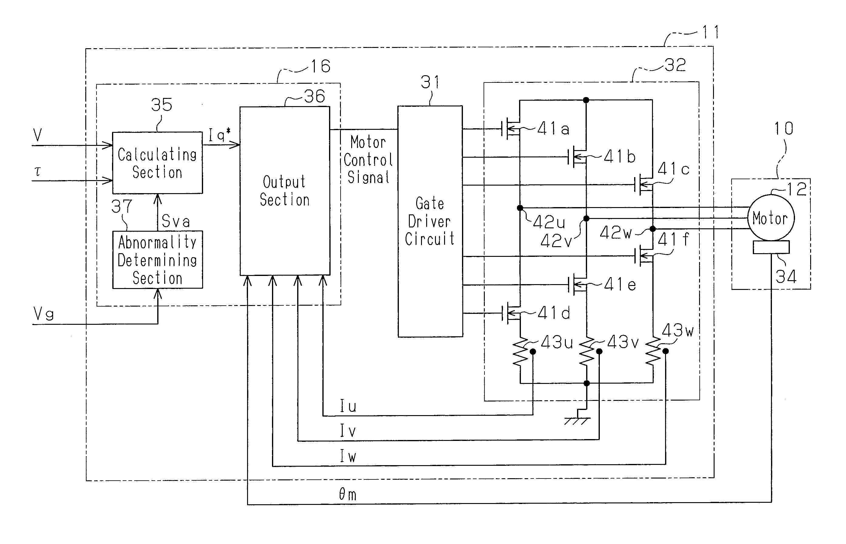
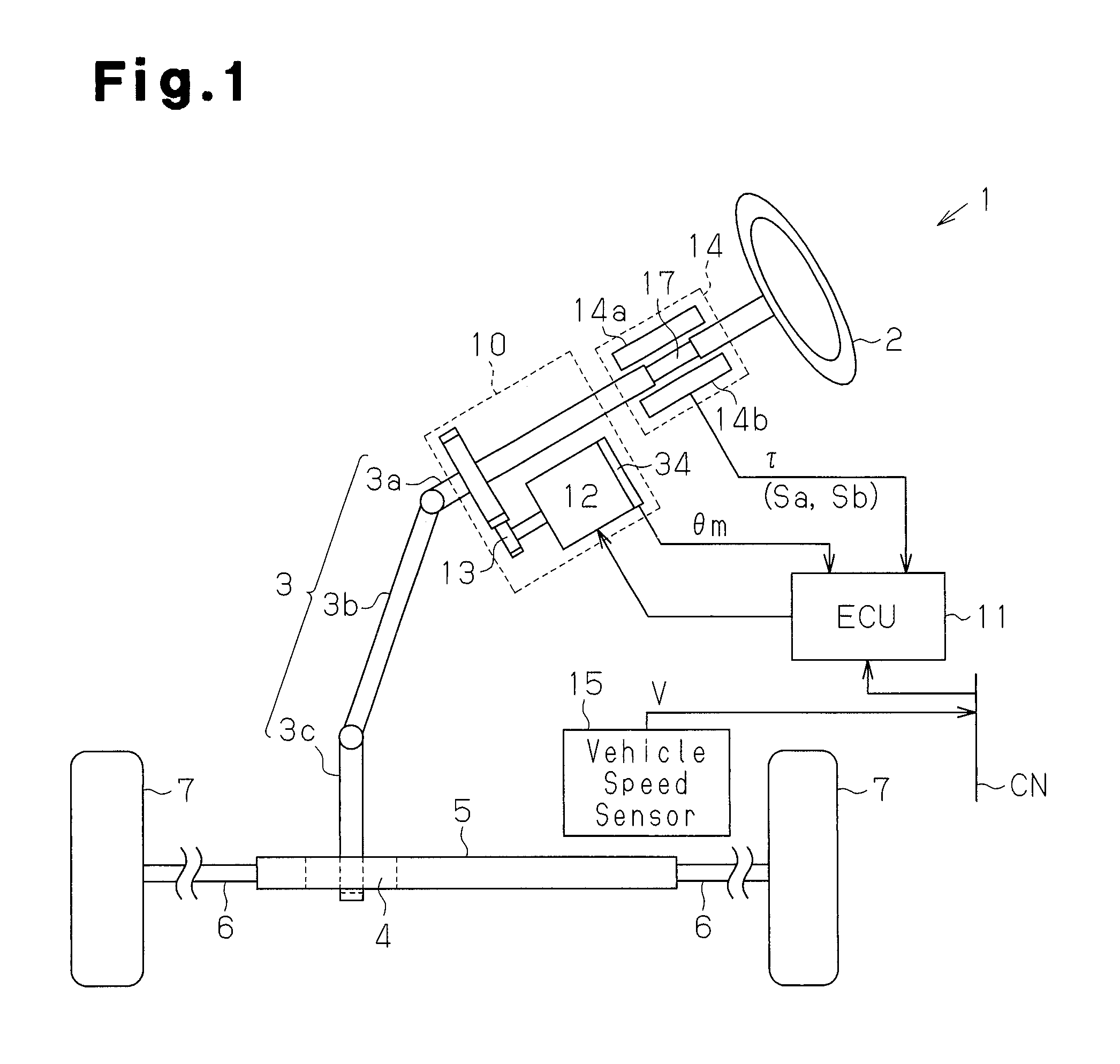
[0036]The first embodiment in which the present invention is implemented in an electric power steering apparatus (EPS) of column type will now be described with reference to FIGS. 1 to 7.

[0037]As shown in FIG. 1, a steering wheel 2 is fixed to a steering shaft 3 and also coupled to a rack shaft 5 via a rack and pinion mechanism 4. In response to a driver's operation of the steering wheel 2, the steering shaft 3 rotates. Then, the rotation of the steering shaft 3 is converted into reciprocal linear motion of the rack shaft 5 by the rack and pinion mechanism 4.

[0038]The steering shaft 3 includes a column shaft 3a, intermediate shaft 3b, and pinion shaft 3c coupled together. A torsion bar 17 is attached to an intermediate part of the column shaft 3a. Tie rods 6 are coupled to both ends of the rack shaft 5. The linear motion of the rack shaft 5 is transmitted to a knuckle, not shown, via the tie rods 6. Consequently, the steering angle of wheels 7 to be turned is changed, and thus the t...

second embodiment

[0069]Next, referring to FIGS. 8 to 10, the second embodiment according to the present invention will be described. In the second embodiment, detailed descriptions of parts identical to those in the first embodiment are omitted.

[0070]As shown in FIG. 8, a calculating section 135 includes a limiting map 51 that limits an electric current command value Iq** output from a calculation map 50. A switching section 152 includes a contact point 152a connected to the calculation map 50, a contact point 152n connected to a command value memory, a contact point 152b connected to a limiting map 51, and a contact point 152c connected to an output section 36. Based on the state of the voltage Vg of a gate driver power source 29, the switching section 152 is switched as follows. If the voltage Vg of the gate driver power source 29 is equal to or higher than a first voltage threshold value α1, the switching section 152 connects a contact point 152a and a contact point 152c. Consequently, the electr...

third embodiment

[0081]Next, referring to FIG. 4 and FIGS. 11 to 14, the third embodiment according to the present invention will be described. In the third embodiment, detailed descriptions of parts identical to those in the first embodiment are omitted.

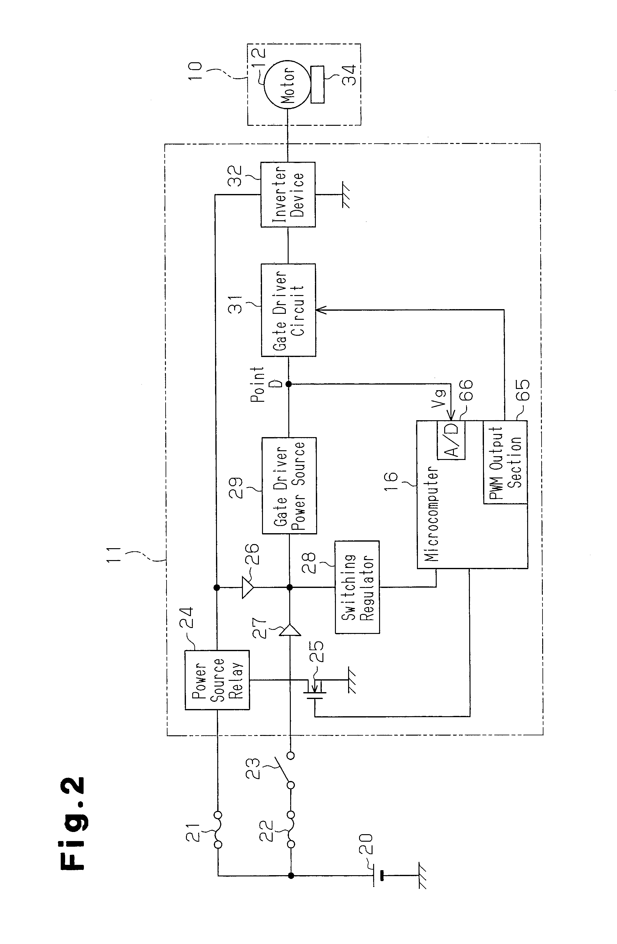
[0082]As shown in FIG. 11, the power source voltage Vb of an inverter device 32 is taken into an A / D terminal 66 of a microcomputer 16 from a point d2, which is midway between a power source relay 24 and the inverter device 32, after divided by voltage dividing resistances R3 and R4. Also, the voltage Vg of a gate driver power source 29 is taken into the A / D terminal 66 from a point d1, which is midway between the gate driver power source 29 and a gate driver circuit 31, after divided by voltage dividing resistances R1 and R2.

[0083]As shown in FIG. 12, based on a difference between the voltage Vg of the gate driver power source 29 and the power source voltage Vb of the inverter device 32, which are taken into the A / D terminal 66, an abnormality dete...


PUM


Abstract

An electric power steering apparatus includes an EPS actuator that applies assist force to a steering system, and an ECU that controls operation of the EPS actuator. The ECU includes an inverter device, a gate driver circuit, a gate driver power source, a microcomputer, and the like. The microcomputer switches assist control to assist stop control, based on an indication of a voltage decrease in the gate driver power source.

Description

TECHNICAL FIELD[0001]The present invention relates to an electric power steering apparatus.BACKGROUND ART[0002]In recent years, vehicles have been equipped with power steering apparatus for assisting a driver's steering operation. As a power steering apparatus, an electric power steering apparatus (EPS) is widely used, which has a brushless DC motor serving as a drive source. Generally, an EPS incorporates an inverter device for driving a brushless DC motor.[0003]Power for an inverter device is supplied by a battery mounted in a vehicle. The inverter device comprises six semiconductor switching elements (FETs): three on the battery side, and three on the ground side. In order to drive the three FETs on the battery side, voltage higher than the battery voltage has to be supplied to the respective gates of these FETs. For this reason, an EPS includes a gate driver power source separately from the battery.[0004]However, the conventional EPS is not provided with a means for specifying w...

Claims


Application Information

Patent Timeline
IPC IPC(8): H02P6/08
CPCH02P6/08B62D5/0484B62D5/0481B62D5/04
Inventor KAWAMURA, HIROSHI
Owner JTEKT CORP
Why Eureka
Try Eureka