Magnetic core, inductor and module including inductor

a technology of inductor and magnetic core, which is applied in the direction of magnetic bodies, continuously variable inductance/transformers, transportation and packaging, etc., can solve the problems of brittle ceramics such as ltcc, large heat generation of inductor, and complex structure of module, etc., to achieve the effect of improving the thermal conductivity of the magnetic core, increasing the volume filling ratio, and improving the thermal conductivity

Active Publication Date: 2014-08-07
TOKIN CORP
View PDF9 Cites 34 Cited by
  • Summary
  • Abstract
  • Description
  • Claims
  • Application Information

AI Technical Summary

Benefits of technology

[0009]It is therefore an object of the present invention to provide a module having a simple structure which can efficiently radiate heat generated by an inductor. It is also an object of the present invention to provide a magnetic core and an inductor which are suitable for the module.
[0013]The magnetic core of the inductor of the module according to the first aspect of the present invention is made of the soft magnetic metal material. Accordingly, the thermal conductivity of the magnetic core can be improved by increasing the volume filling ratio (volume ratio) of the soft magnetic metal material. Moreover, since the radiating surface of the magnetic core, whose thermal conductivity can be thus-improved, is arranged to be radiatable heat outward, the heat generated by the inductor can be efficiently radiated. Moreover, since the magnetic core according to the second aspect of the present invention has elasticity, the magnetic core can be processed easily. Accordingly, it is relatively easy to form the magnetic core and the inductor each of which have a size and a shape suitable for the module.

Problems solved by technology

Especially, an inductor tends to generate large heat.
Accordingly, the module tends to have a complicated structure and a large size.
Moreover, ceramics such as the LTCC is a brittle material.
Accordingly, the LTCC inductor is easily damaged when pressed against the other member, for example, the member for radiating the heat.
Moreover, as described in Patent Document 1, the LTCC inductor has low thermal conductivity.
Accordingly, even when the module has the member for radiating the heat, it is difficult to radiate the heat sufficiently.
Moreover, the aforementioned drawback is not limited to the LTCC inductor.
In general, although an inductor is a main heat generator in a module, an existing inductor has low thermal conductivity.
Accordingly, it is difficult to efficiently radiate the heat generated by the inductor.
The aforementioned process is cumbersome.
Thus, it is not easy to form an inductor having a shape and a size which are suitable for a module.

Method used


Image

  • Magnetic core, inductor and module including inductor
  • Magnetic core, inductor and module including inductor
  • Magnetic core, inductor and module including inductor

Examples


first embodiment

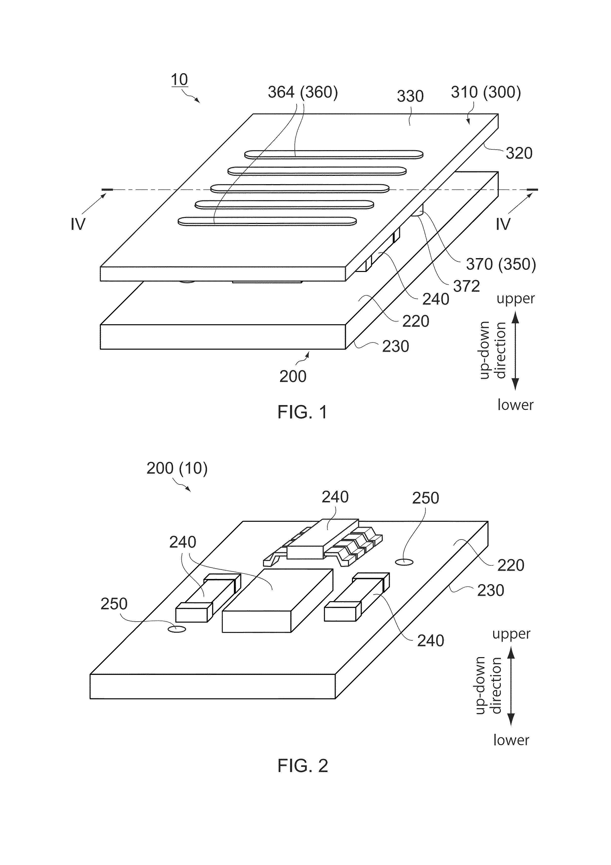
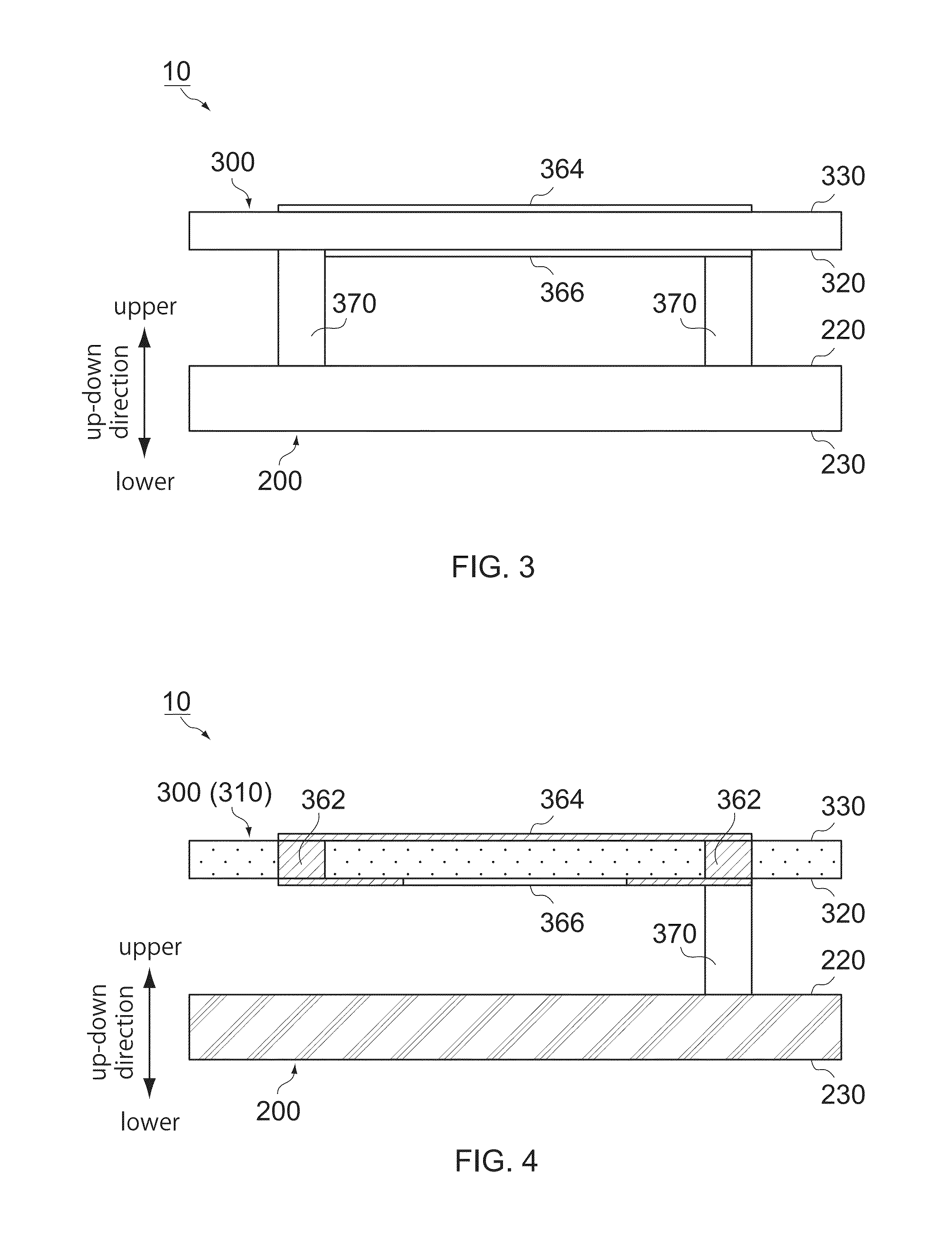
[0045]As shown in FIG. 1, a module (power module) 10 according to a first embodiment of the present invention comprises a circuit board 200 and an inductor 300. The module 10 according to the present embodiment is a power module which is to be installed, for example, in an electronic apparatus (not shown) to supply electric power outward of the module 10. However, the present invention is applicable to a module other than the power module 10.

[0046]As shown in FIGS. 1 to 4, the circuit board 200 has a facing surface 220 and a rear surface 230 which are located at opposite sides to each other in an up-down direction. Each of the facing surface 220 and the rear surface 230 according to the present embodiment is a horizontal plane perpendicular to the up-down direction.

[0047]As shown in FIG. 2, the module 10 is provided with electronic components 240 such as a switching transistor, a power control IC, a capacitor and so on. According to the present embodiment, the electronic components ...

second embodiment

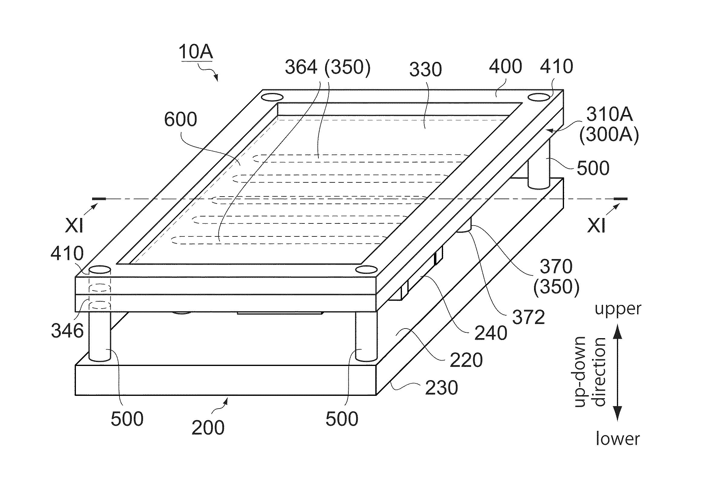
[0070]As can be seen from FIGS. 1 and 10, a module (power module) 10A according to a second embodiment of the present invention is a modification of the module 10 according to the first embodiment (see FIG. 1). The module 10A comprises the circuit board 200 same as that of the module 10, an inductor 300A which is slightly different from the inductor 300 of module 10. Moreover, the module 10A comprises a radiating member 400, a plurality of (according to the present embodiment, four) coupling members 500 and a coating 600, which are not included in the module 10. Hereafter, explanation is mainly made about different points between the module 10A and the module 10.

[0071]As shown in FIGS. 10 and 11, the inductor 300A has a magnetic core 310A and the coil 350. The magnetic core 310A has the almost same structure as the magnetic core 310 (see FIG. 6). However, the magnetic core 310A is formed with four holding holes 346. The holding holes 346 are formed at four corners of the magnetic co...

third embodiment

[0079]As can be seen from FIGS. 10 and 12, a module (power module) 10B according to a third embodiment of the present invention is a modification of the module 10A (see FIG. 10). The module 10B comprises a circuit board 200B which is slightly different from the circuit board 200. Moreover, the module 10B comprises the inductor 300A, the radiating member 400, the coupling members 500 and the coating 600 which are same as those of the module 10A. Hereafter, explanation is mainly made about different points between the module 10B and the module 10A.

[0080]As can be seen from FIGS. 12 and 13, the circuit board 200B has a box-like shape. In detail, the circuit board 200B has four sidewalls 210. The sidewalls 210 extend upward from four sides of the facing surface 220, respectively. For example, the thus-configured circuit board 200B can be formed of a plurality of circuits boards each having a plate-like shape. According to the present embodiment, any electronic component 240 is not mount...


PUM

PropertyMeasurementUnit
Young's modulusaaaaaaaaaa

Abstract

A module comprises a circuit board and an inductor. The circuit board has a facing surface and a rear surface which are located at opposite sides to each other in an up-down direction. The inductor has a magnetic core and a coil. The magnetic core is made of a soft magnetic metal material. The magnetic core has a facing surface and a radiating surface which are located at opposite sides to each other in the up-down direction. The facing surface of the magnetic core is arranged to face the facing surface of the circuit board in the up-down direction. The radiating surface of the magnetic core is arranged to be radiatable heat outward. The coil has a coil portion and a connection end. The coil portion winds, at least in part, the magnetic core. The connection end is connected to the facing surface of the circuit board.

Description

CROSS REFERENCE TO RELATED APPLICATIONS[0001]An applicant claims priority under 35 U.S.C. §119 of Japanese Patent Applications No. JP2013-019649 filed Feb. 4, 2013 and No. JP2013-198965 filed Sep. 25, 2013.BACKGROUND OF THE INVENTION[0002]This invention relates to a module comprising a circuit board and an inductor. For example, the module is a power module which is to be installed in an electronic apparatus to supply electric power. This invention also relates to a magnetic core and an inductor which are suitable for the module.[0003]Generally, an electric component mounted on a circuit board, for example, a switching transistor, a power control Integrated Circuit (IC) or an inductor, generates heat. As the size of the circuit board is reduced, the heat per unit volume increases. Especially, an inductor tends to generate large heat. Accordingly, a module including a circuit board and an inductor is required to have a structure for efficiently radiating heat outward. For example, a ...

Claims


Application Information

Patent Timeline
Patent Type & Authority Applications(United States)
IPC IPC(8): H01F27/08H01F17/04
CPCH01F17/04H01F27/085H01F17/0013H01F17/0033H01F27/22B22F3/11H01F1/14766B22F3/1103H01F1/14791H01F1/14775B22F3/1109H01F27/255B22F2003/1106Y10T428/32
Inventor CHATANI, KENICHIIKEDA, KENJITSUDA, TOSHINORI
Owner TOKIN CORP
Why Eureka
Try Eureka