Methods for Anti-islanding in distributed-source electrical power generation and distribution systems and electrical systems and apparatus using same

Inactive Publication Date: 2014-08-14
AEG POWER SOLUTIONS BV
View PDF9 Cites 28 Cited by
  • Summary
  • Abstract
  • Description
  • Claims
  • Application Information

AI Technical Summary

Benefits of technology

[0022]Advantageously, the anti-islanding functions realized by the embodiments of the principles of the present invention allow for fast detection of an interruption in grid power, even if the inverter output voltage, current, and phase initially do not significantly ch

Problems solved by technology

However, if the load is not a purely resistive, and hence the current and voltage are not in phase, the power must be delivered to the load as active and reactive parts.
To process the Reactive Power (RP), the Active Power (AP) delivered to the load must be decreased and the inverter unit becomes less efficient.
The impedance of the grid is so low that it is nearly impossible to modify the grid voltage magnitude.
A potentially dangerous condition known as islanding occurs on an electrical utility grid when the primary source supplying power to the grid o

Method used


Image

  • Methods for Anti-islanding in distributed-source electrical power generation and distribution systems and electrical systems and apparatus using same
  • Methods for Anti-islanding in distributed-source electrical power generation and distribution systems and electrical systems and apparatus using same
  • Methods for Anti-islanding in distributed-source electrical power generation and distribution systems and electrical systems and apparatus using same

Examples


Embodiment Construction

[0028]The principles of the present invention and their advantages are best understood by referring to the illustrated embodiment depicted in FIGS. 2-3 of the drawings, in which like numbers designate like parts.

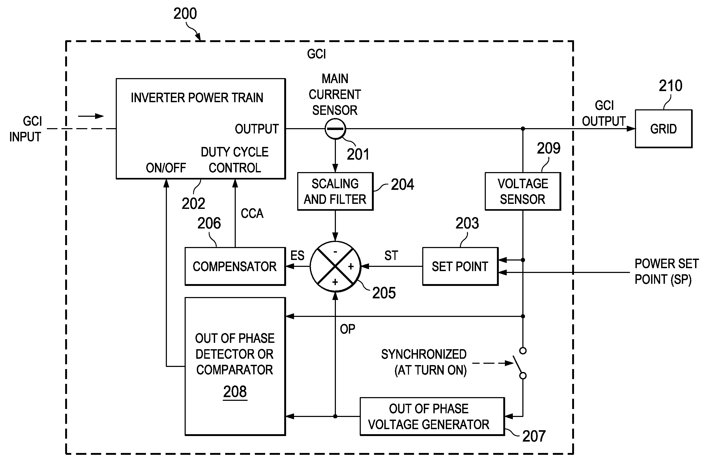
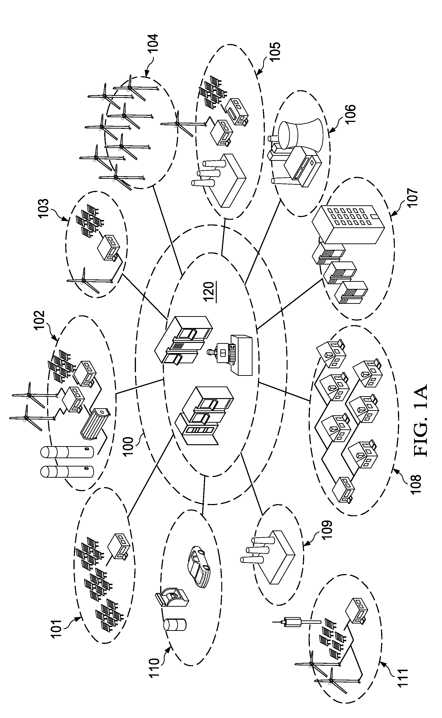
[0029]FIG. 2 is a block diagram of an exemplary Grid Connected Inverter (GCI) 200 with anti-islanding (grid-disconnect) functionality according to one embodiment of the present inventive principles. GCI 200 can advantageously be applied to the systems and subsystems shown in FIG. 1A, including inverters, uninterrupted power supply (UPS) systems, and AC / DC converters, among others.

[0030]Generally, the power train current is compared with an reference current ST, which is an image of the requested current that the inverter power train must deliver to the grid, as shaped by the waveform of the grid voltage. Reference current ST is generated from the power set point input signal SP, which is a constant value, dimensioned in watts or kilowatts. For the case where the GCI output v...


PUM


Abstract

A method of detecting an interruption of grid electrical power at an output of an inverter power train coupled to an electrical grid includes generating a reference waveform representing a power train output current waveform with a current control loop. An out-of-phase control signal is generated, which is synchronized and out-of-phase with a grid voltage waveform, with a voltage control loop coupled to the output of the inverter power train, the voltage control loop having a gain proportional to an inverter power train load impedance. The reference waveform and the out-of-phase control signal are combined to generate a power train control signal for producing a small phase difference between the inverter power train output current waveform and the grid voltage waveform. The inverter power train output is monitored for a change and the inverter power train is turned off in response to a change in the inverter power train output caused by an increase in inverter power train load impedance resulting from an interruption in the grid electrical power.

Description

CROSS-REFERENCE TO RELATED APPLICATION[0001]The present applications claims the benefit of U.S. Provisional Patent Application Ser. No. 61 / 764,700, filed Feb. 14, 2013.[0002]The following co-pending and co-assigned application contains related information and is hereby incorporated by reference for all purposes:[0003]U.S. patent application Ser. No. 14 / 141,175 (Attorney Docket No. 515225.000014), filed Dec. 27, 2013, for Methods for Controlling Electrical Inverters and Electrical Inverters Using The Same.FIELD OF INVENTION[0004]The present invention relates in general to electrical power generation and distribution systems, and in particular to methods for anti-islanding in distributed-source electrical power generation and distribution systems and electrical systems and apparatus using the same.BACKGROUND OF INVENTION[0005]In a traditional electrical utility grid model, the voltage and associated current are provided by large scale utility power plants running from expendable energ...

Claims


Application Information

Patent Timeline
IPC IPC(8): H02H3/48
CPCH02H3/48H02J3/38H02J3/388H02J3/44
Inventor ELLIOTT, II, WILLIAM DEWEY
Owner AEG POWER SOLUTIONS BV
Why Eureka
Try Eureka