Power converter

a power converter and converter technology, applied in the direction of motor/generator/converter stopper, dynamo-electric converter control, dynamo-electric gear control, etc., can solve the problems of increasing the loss of devices in the three-phase electrolytic capacitor-less inverter, the rate of voltage utilization is reduced, and the device loss is reduced. , the effect of effective realization

Active Publication Date: 2014-08-21
DAIKIN IND LTD
View PDF7 Cites 33 Cited by
  • Summary
  • Abstract
  • Description
  • Claims
  • Application Information

AI Technical Summary

Benefits of technology

[0026]According to the first aspect of the invention, since pulsation of the output current of the inverter circuit (4) can be reduced, failure caused due to pulsation of the direct current link voltage can be reduced, and such reduction allows over-modulation control.
[0027]According to the second aspect of the invention, the advantage of the first aspect of the invention can be more effectively realized.
[0028]According to the third aspect of the invention, in the so-called “six-step ...

Problems solved by technology

Typically, over-modulation control is not performed in a three-phase electrolytic capacitor-less inverter, resulting in a...

Method used


Image

  • Power converter
  • Power converter
  • Power converter

Examples


first embodiment

of the Invention

[0040]

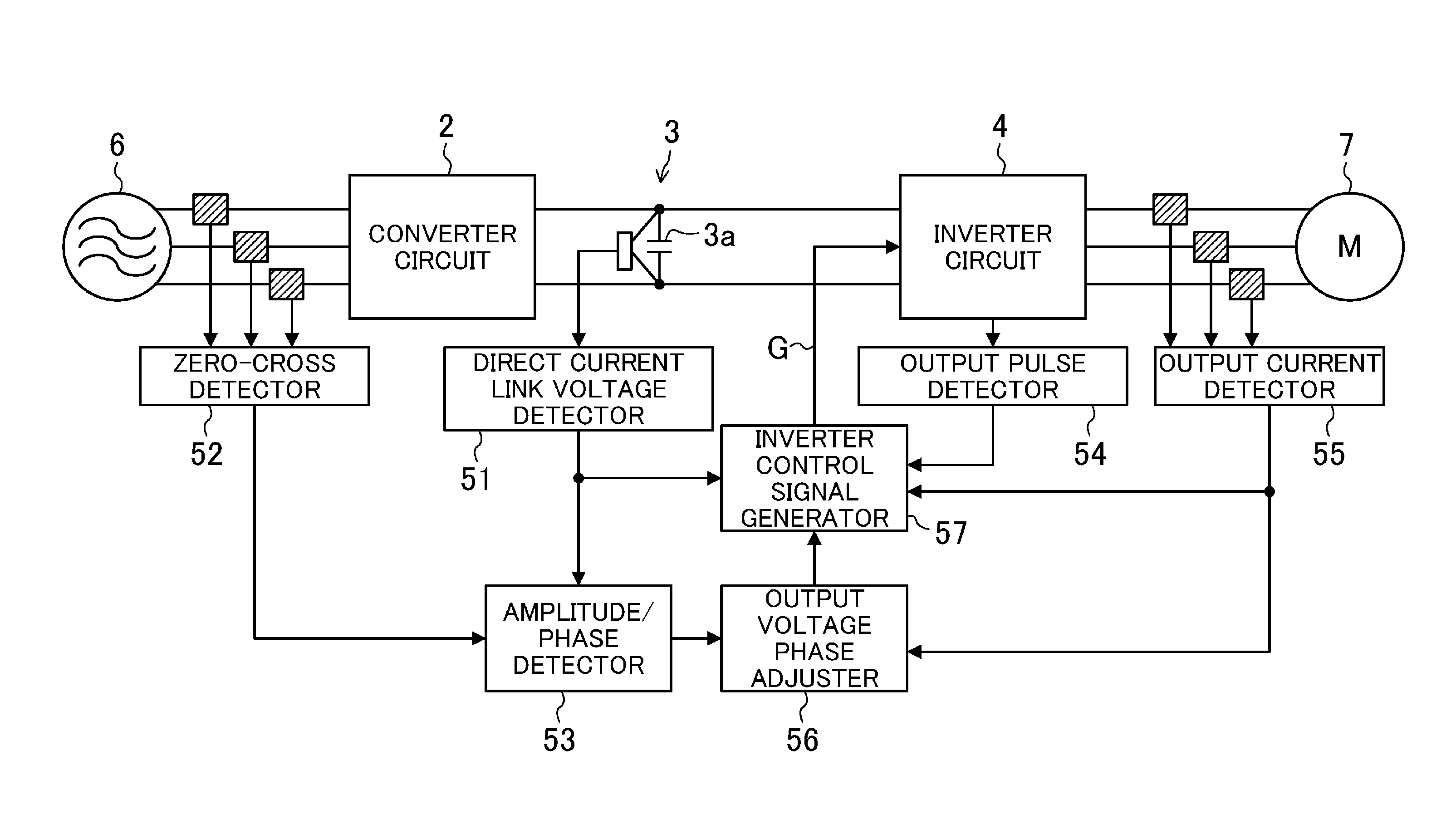
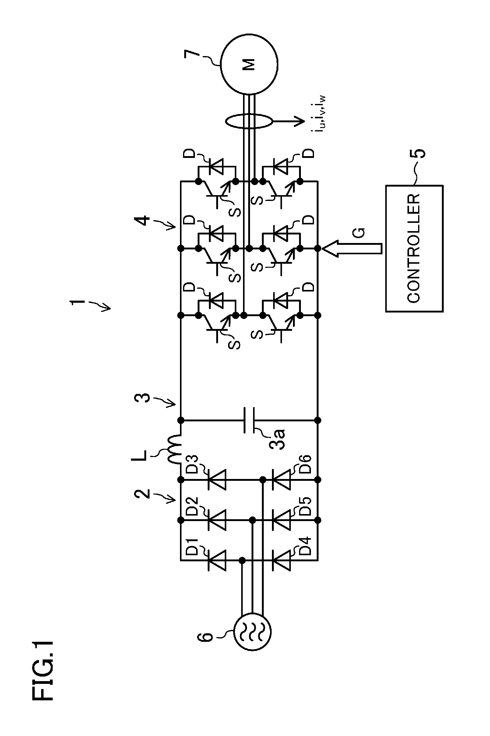
[0041]FIG. 1 is a block diagram illustrating the configuration of a power converter (1) of a first embodiment of the present disclosure. Referring to FIG. 1, the power converter (1) includes a converter circuit (2), a direct current link (3), an inverter circuit (4), and a controller (5). The power converter (1) is configured to convert an alternating current power supplied from a three-phase alternating current power supply (6) to a power having a predetermined frequency to supply the converted power to a motor (7). Note that the motor (7) of the present embodiment is a permanent magnet synchronous motor. More specifically, the motor (7) of the present embodiment is an interior permanent magnet motor (hereinafter sometimes referred to as an “IPM motor”). The motor (7) is configured to drive, e.g., a compressor provided in a refrigerant circuit of an air conditioner.

[0042]2)>

[0043]The converter circuit (2) is connected to the three-phase alternating current pow...

second embodiment

of the Invention

[0085]A power converter (1) of a second embodiment controls a voltage phase using the output torque of a motor (7) as a reference, instead of using an output current as the reference.

[0086]The output torque of the motor (7) can be obtained by a cross product of a current vector (i) and an armature interlinkage magnetic flux vector. Specifically, the output torque can be represented by the following expression.

i·Ψ·sin φ  [Second Expression]

i: MAGNITUDE OF CURRENT VECTOR

Ψ: MAGNITUDE OF INTERLINKAGE MAGNETIC FLUX VECTOR

φ: ANGLE BETWEEN BOTH VECTORS

[0087]The power converter (1) of the present embodiment controls the voltage phase using the output torque of the motor (7) as the reference, instead of using the output current as the reference. The motor output torque is determined depending on a motor voltage, a motor current, and a motor rotational speed. Thus, if the voltage phase is controlled, the torque can be controlled. Specifically, the torque can be controlled in s...

third embodiment

of the Invention

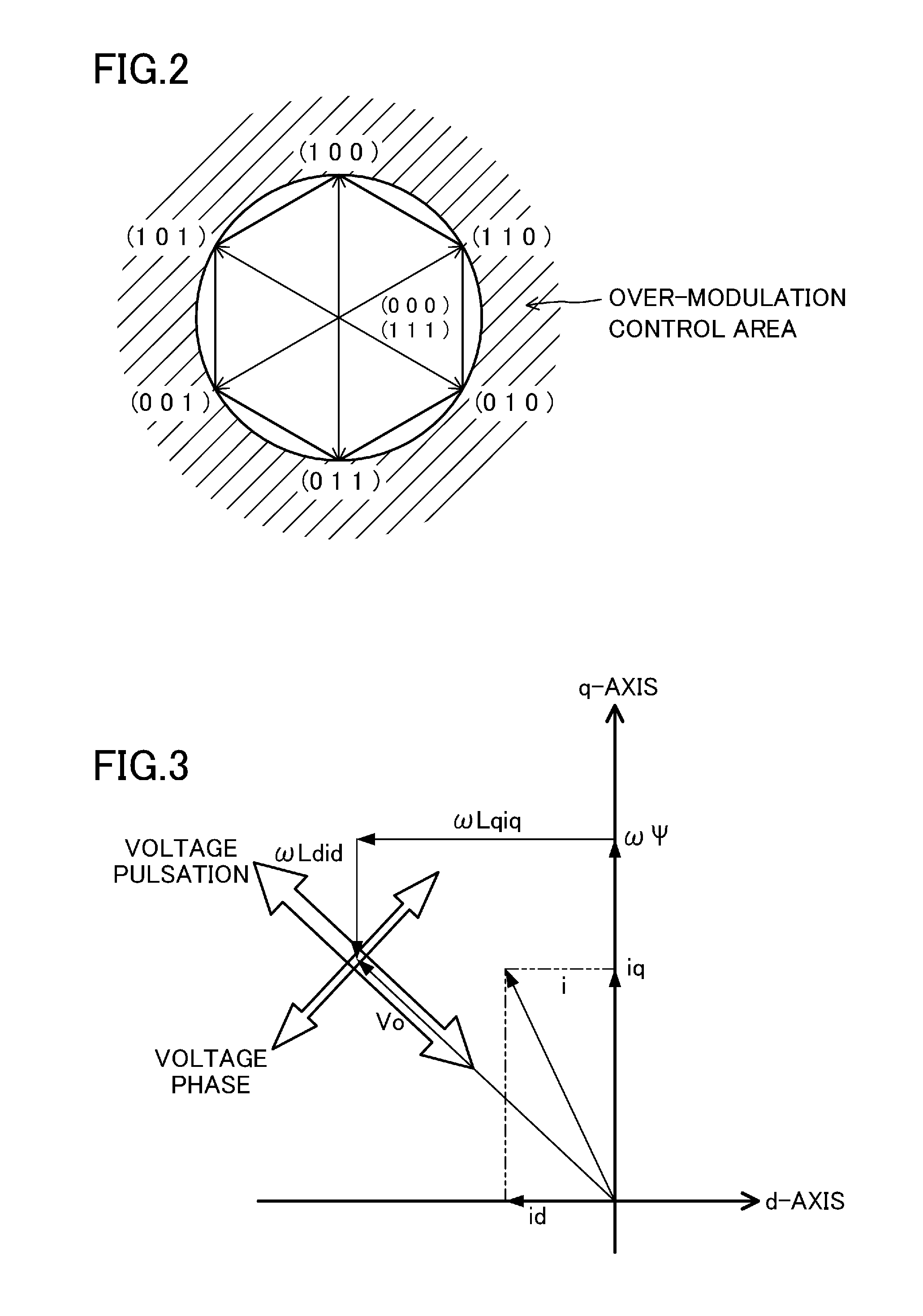
[0089]A power converter (1) of a third embodiment controls a voltage phase using the output power factor of an inverter circuit (4) as a reference, instead of using an output current as the reference. The output power factor is determined depending on a relationship between the phase of a resultant voltage vector (V0) and the phase of a current vector (i). Thus, if the voltage phase is controlled, the output power factor can be controlled. Specifically, the output power factor can be controlled in such a manner that feedback control is performed in the output voltage phase adjuster (56) to change the voltage phase.

[0090]Improvement of the output power factor reduces the size of the inverter circuit (4) and the size of a motor (7).


PUM


Abstract

In a power converter, vibration and noise of a motor due to pulsation of a direct current link voltage are reduced. An inverter circuit is provided, which is configured to convert a direct current link voltage having a pulsating component to an alternating current to output the alternating current to a permanent magnet synchronous motor. A controller is provided, which is configured to control the inverter circuit by vector control and which, in a control state in which fundamental voltage vectors do not include a zero vector (voltage vector for which a motor terminal voltage is zero), performs such control that the phase of a resultant voltage vector of a d-axis voltage vector and a q-axis voltage vector of the permanent magnet synchronous motor varies depending on pulsation.

Description

TECHNICAL FIELD[0001]The present disclosure relates to a power converter configured to convert, by switching, an input to an alternating current output with a predetermined frequency and a predetermined voltage.BACKGROUND ART[0002]Conventionally, a power converter including an inverter circuit has been known. The inverter circuit is configured to convert, by switching control, a direct current power to an alternating current power having a variable frequency and a variable voltage with high efficiency.[0003]Examples of the power converter of this type include a so-called “electrolytic capacitor-less inverter circuit” using a low-capacity smoothing capacitor for a direct current link (see, e.g., Patent Document 1). In the electrolytic capacitor-less inverter circuit, e.g., a smoothing capacitor having a low capacity of about several hundred microfarads is provided on an output side of a diode rectifier circuit, instead of providing a conventional high-capacity smoothing capacitor (el...

Claims


Application Information

Patent Timeline
IPC IPC(8): H02P21/00H02P21/02H02P21/05H02P23/02H02P23/04H02P23/26H02P27/04H02P27/08
CPCH02P21/0039H02P21/05H02P21/06H02P27/08
Inventor ZHOU, YUEQIANGMAEDA, TOSHIYUKI
Owner DAIKIN IND LTD
Why Eureka
Try Eureka