Nanolaser generator using graphene electrode and method for manufacturing the same

a graphene electrode and generator technology, applied in the direction of lasers, optical resonator shape and construction, semiconductor lasers, etc., can solve the problems of complicated techniques and disturbances in the generation of laser light, and achieve the effects of reducing the process required for generating, good light penetration, and easy transformation

Active Publication Date: 2014-08-21
KOREA UNIV RES & BUSINESS FOUND
View PDF2 Cites 15 Cited by
  • Summary
  • Abstract
  • Description
  • Claims
  • Application Information

AI Technical Summary

Benefits of technology

[0030]However, the nanolaser generator of the present disclosure allows easy passage of electricity and good penetration of light. Therefore, even though a graphene electrode is positioned adjacent thereto, the light is substantially not absorbed or diffused. In addition, a nanolaser may be generated by injecting electricity using the graphene electrode which is as soft as a toilet tissue and thus easily transformable.
[0031]In addition, the nanolaser generator of the present disclosure may reduce the processes required for generating a nanolaser by half in comparison to a general electric-driven nanolaser generator and generate a nanolaser just with a micro current. Therefore, it is possible to commercialize and mass-produce an electric-driven nanolaser. Moreover, if a nanolaser emitted from the nanolaser generator is used, an optical element (a device for controlling movement of light, a laser or an LED) may be easily moved with electricity, which may advance the development of an optical computer.

Problems solved by technology

In case of a general nanolaser generator using a metal, if the metal is positioned near a laser, the laser light is absorbed by a metal electrode or diffused, which disturbs the generation of laser light.
The electric-driven general nanolaser needs a side p-i-n joint which is well aligned with nanocavity or needs to dispose an electrode of a sub-micron size at a suitable position with the accuracy of a sub-wavelength scale, which are however complicated techniques.

Method used


Image

  • Nanolaser generator using graphene electrode and method for manufacturing the same
  • Nanolaser generator using graphene electrode and method for manufacturing the same
  • Nanolaser generator using graphene electrode and method for manufacturing the same

Examples


Embodiment Construction

[0051]The present disclosure is directed to providing a nanolaser generator using a graphene electrode, which may generate a nanolaser with a micro current while reducing the processes of the nanolaser generator, which is driven by electricity to generate a nanolaser, by half; a method for manufacturing the same; and a single nanopillar LED using the same.

[0052]Hereinafter, the present disclosure will be described in detail.

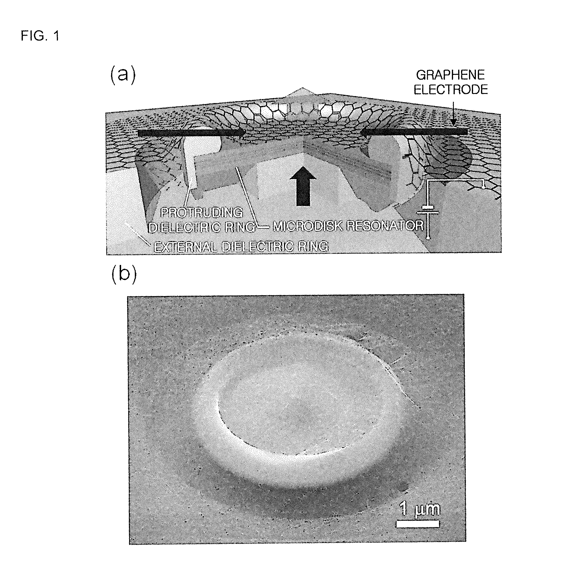
[0053]FIG. 1a is a cross-sectional view showing a nanolaser generator manufactured according to an embodiment of the present disclosure, and FIG. 1b is an SEM photograph showing the nanolaser generator manufactured according to an embodiment of the present disclosure.

[0054]As shown in FIGS. 1a and 1b, the nanolaser generator using a graphene electrode according to the present disclosure includes a microdisk resonator, a protruding dielectric ring, an external dielectric ring and a transparent graphene electrode. At this time, the dielectric ring is made of a diel...


PUM

PropertyMeasurementUnit
transmittanceaaaaaaaaaa
thicknessaaaaaaaaaa
thicknessaaaaaaaaaa

Abstract

The present disclosure relates to a nanolaser generator using a transparent graphene electrode, a method for manufacturing the same, and a single nanopillar LED using the same. The nanolaser generator includes a microdisk resonator, a protruding dielectric ring provided to surround a boundary surface of the microdisk resonator, an external dielectric ring provided at an outer side of the microdisk resonator, and a transparent graphene electrode provided at upper surfaces of the microdisk resonator, the protruding dielectric ring and the external dielectric ring. Therefore, the processes required for generating a nanolaser may be reduced by half in comparison to a general technique, and a nanolaser may be generated just with a micro current.

Description

CROSS-REFERENCE TO RELATED APPLICATIONS[0001]This application claims priority under 35 U.S.C. §119 to Korean Patent Application No. 10-2013-0018747 filed on Feb. 21, 2013, in the Korean Intellectual Property Office, the disclosure of which is incorporated herein by reference in its entirety.TECHNICAL FIELD[0002]The present disclosure relates to a nanolaser generator using a transparent graphene electrode, a method for manufacturing the same, and a single nanopillar LED using the same.BACKGROUND[0003]Nanolasers based on a semiconductor have rotationally evolved from a vertical cavity surface emitting laser of one-dimensional photonic crystal representing a first generation nanolaser, via a two-dimensional photonic crystal laser of a second generation, to a nano-ladder laser of a third generation, which looks like a one-dimensional nanolaser.[0004]In detail, in 1989, Bell Laboratories in U.S. has successfully made a vertical cavity surface emitting laser (VCSEL), which is a novel semi...

Claims


Application Information

Patent Timeline
Patent Type & Authority Applications(United States)
IPC IPC(8): H01S3/038H01L33/38H01L33/40
CPCH01S3/038H01L33/40H01L33/38H01L33/20H01L33/44H01S5/1075H01S5/04253H01S5/04254H01S5/04252H01S3/083H01S3/05
Inventor PARK, HONG-GYUKIM, YOON-HOHWANG, MINSOOKWON, SOON-HONG
Owner KOREA UNIV RES & BUSINESS FOUND
Why Eureka
Try Eureka