

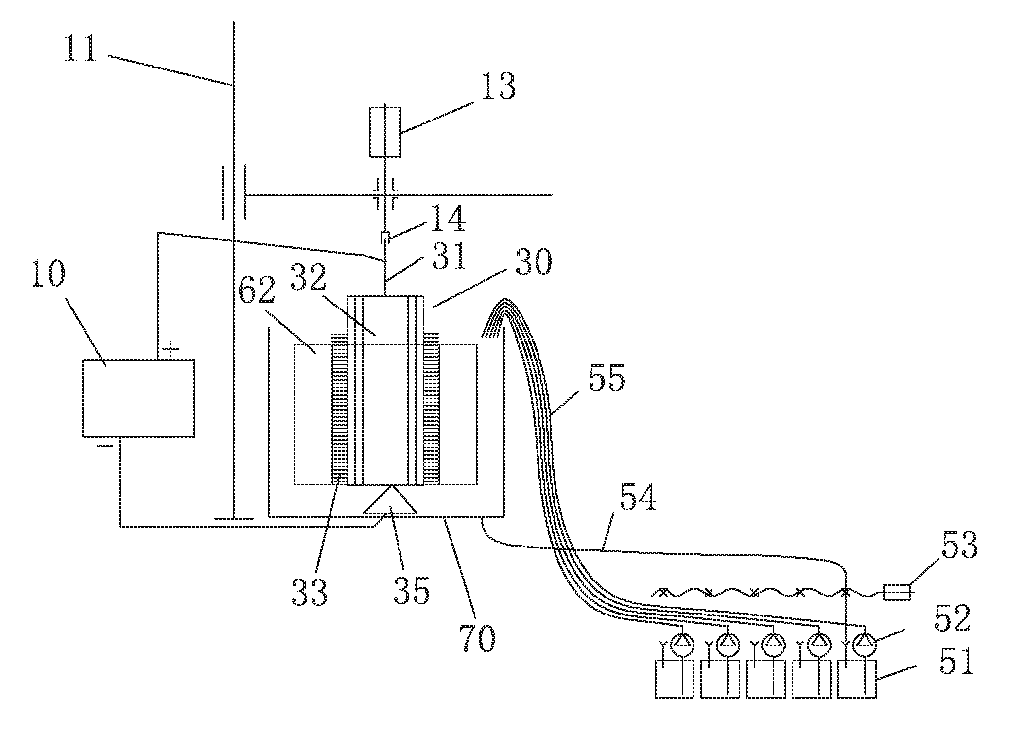
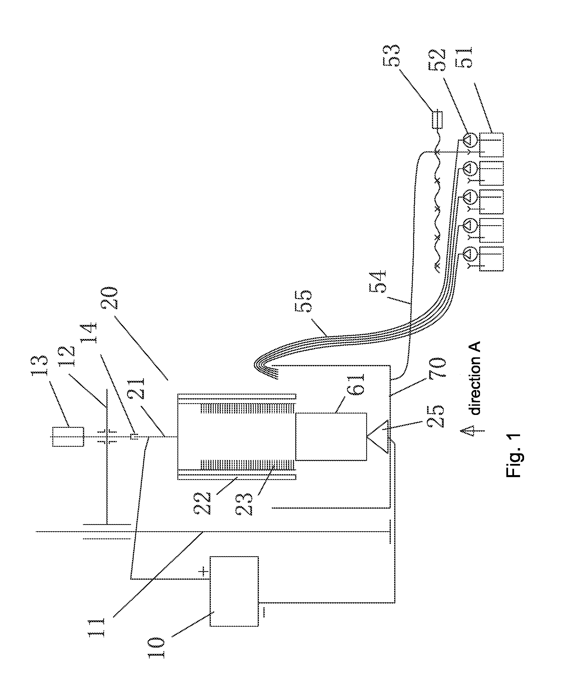
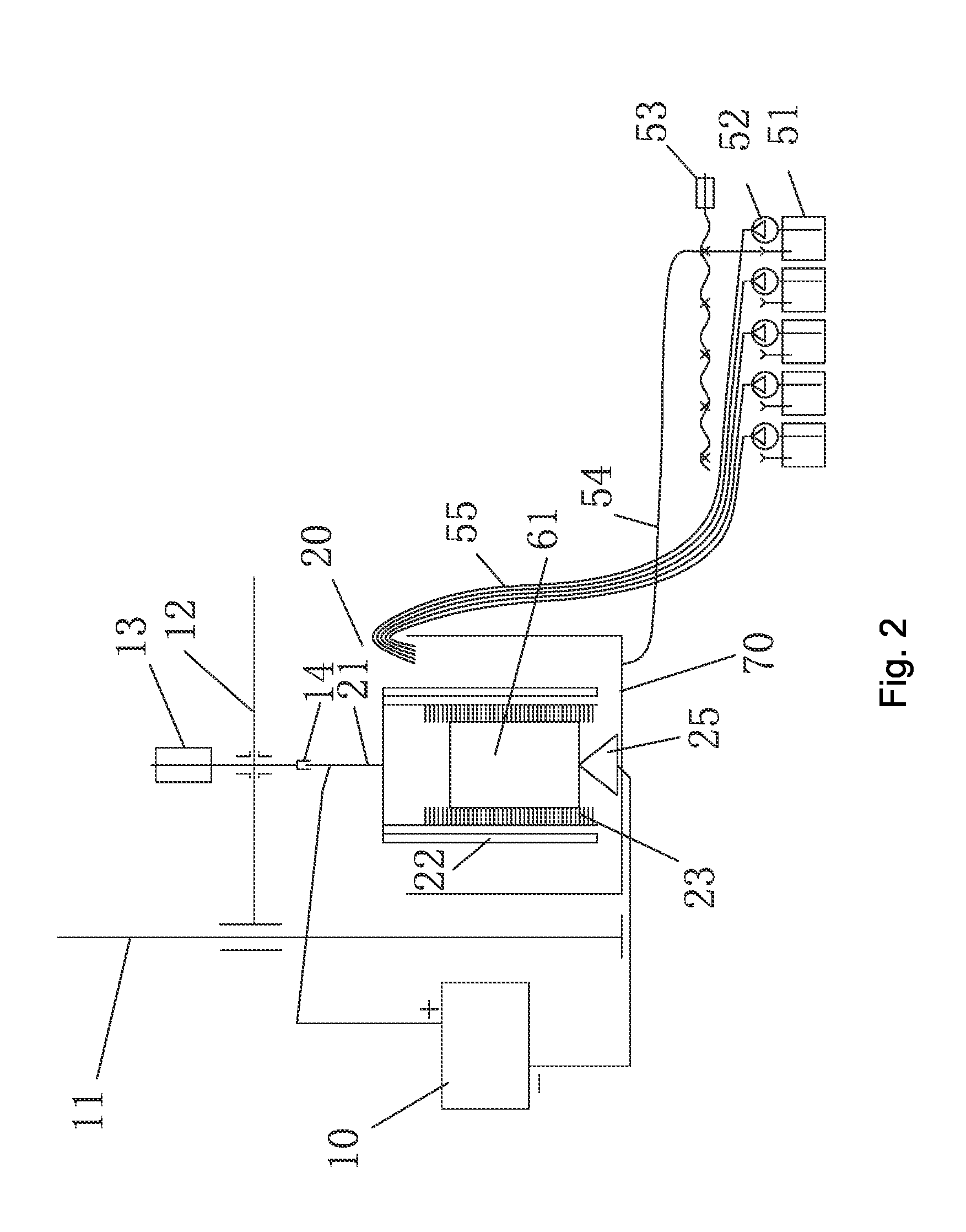
Electrical brush plating system and method for metal parts
a technology of electrical brush and metal parts, applied in the direction of electrolysis process, electrolysis components, cells, etc., can solve the problems of low degree of automation, low working efficiency, and many defects in the existing electrical brush plating technology, so as to improve the quality of the plated layer, improve the electrodeposition rate, and effectively avoid the effect of generation
- Summary
- Abstract
- Description
- Claims
- Application Information
AI Technical Summary
Benefits of technology
Problems solved by technology
Method used
Image

Examples
embodiment 1
[0065]The formula used for the plating solution is: nickel sulfate 280 g / L, boric acid 43 g / L, and nickel chloride 80 g / L. Under the process conditions that the current density is 14 A / dm2, the cathode / anode area ratio is about 2:1, and the plating solution temperature is 50° C., a connecting-rod automatic electrical brush plating is performed and compared with the traditional manual electrical brush plating. The comparison is shown in Table 1.
TABLE 1the comparison between automatic electrical brush plating andmanual electrical brush platingEfficiency ofPlatingelectrical brushsolutionLifetime ofOverall costplatingconsumedplating penof electrical(number per(liter per(numberProductionbrush platingPlating penday)one)per one)yield(Yuan)Manual electrical51.0160%75brush platingAutomatic600.0730095%15electrical brushplatingComparisonIncreased byReducedIncreasedIncreasedReduced byabove 10 timesby 93%by 300 timesby 35%80%
[0066]In combination with the data in Table 1, it can be seen that the ...
embodiment 2
[0068]The formula used for the plating solution is: nickel sulfate 300 g / L, boric acid 45 g / L, and nickel chloride 60 g / L. Under the process conditions that the current density is 16 A / dm2, the cathode / anode area ratio is about 4:1, and the plating solution temperature is 50° C., an automatic electrical brush plating for reproduction (repair) is performed on a waste engine block. The average time spent in reproducing a block is 2.5 h, and metal consumption is 200˜300 g, electricity consumption is 8.5 KW, and the overall reproduction cost for each block is 450 yuan (as will be detailed with reference to Table 2), this not only solves the difficulty that cylinder parts can not be reproduced, but also creates huge economic and social benefits.
TABLE 2the comparison between Steyr engine block reproduction with the deviceand a new engine block productionNewengineOld engineblockblockComparison itemsproductionreproductionComparisonRemarksMaterial consumption350 (billet0.3SavedSince only the...
PUM
| Property | Measurement | Unit |
|---|---|---|
| distance | aaaaa | aaaaa |
| distance | aaaaa | aaaaa |
| cathode current density | aaaaa | aaaaa |
Abstract
Description
Claims
Application Information