Producing cut surfaces in a transparent material by means of optical radiation

Active Publication Date: 2014-09-11
CARL ZEISS MEDITEC AG
View PDF2 Cites 30 Cited by
  • Summary
  • Abstract
  • Description
  • Claims
  • Application Information

AI Technical Summary

Benefits of technology

[0025]The shift of the image field makes it possible to dispense with expensive optical units having an image field large enough to cover the entire treatment zone. However, it may also be pointed out that it is entirely possible to modify the treatment apparatus or the method such that the lateral shift of the position of the focus is done without a shift of the image field if the image field size is greater than the maximum size of the envisaged, sought or produced cut. Such an extension lies within the scope of the invention. The advantage is then retained that the shift of the focus can be ca

Problems solved by technology

The focus can therefore be adjusted along the optical axis only very slowly as rapid movement of the collimator would result in undesired vibrations and thermal loading of the handle.
Moreover, the use of an optical fiber at

Method used


Image

  • Producing cut surfaces in a transparent material by means of optical radiation
  • Producing cut surfaces in a transparent material by means of optical radiation
  • Producing cut surfaces in a transparent material by means of optical radiation

Examples


Embodiment Construction

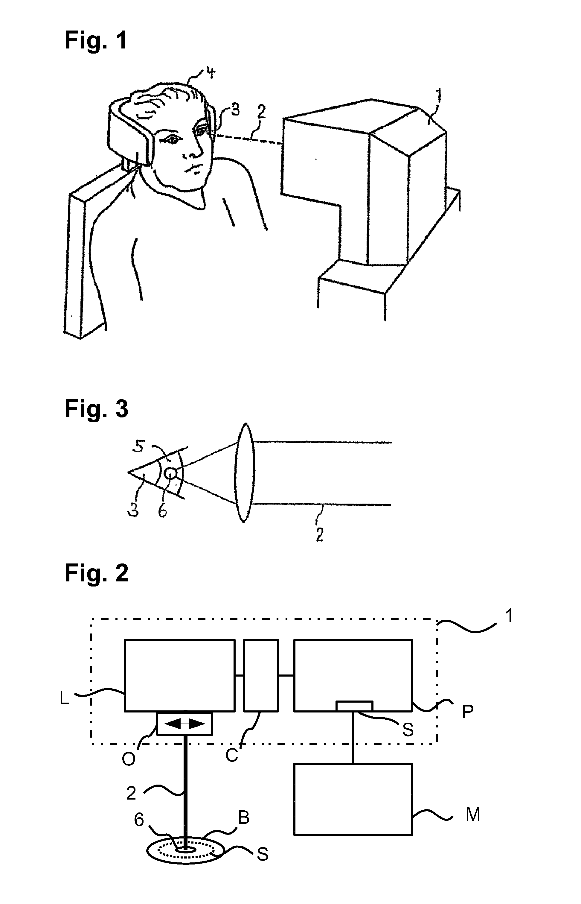
[0049]FIG. 1 shows a treatment apparatus 1 for eye surgery. For example, an eye-surgery process which is similar to that described in EP 1 159 986 A2 and U.S. Pat. No. 5,549,632 can be carried out with it. The treatment apparatus 1 produces a material cutting in transparent material by means of treatment laser radiation 2. This material cutting can be e.g., a production of cuts, in particular the treatment apparatus for correcting defective vision can generate a change on an eye 3 of a patient 4. The defective vision can include hyperopia, myopia, presbyopia, astigmatism, mixed astigmatism (astigmatism in which there is hyperopia in one direction and myopia in a direction at right angles thereto), aspheric errors and higher-order aberrations. The material cutting can be used in the field of corneal surgery but also on other tissues of the eye, e.g., in cataract surgery. While reference is made to eye surgery below, this is to be understood in each case only by way of example and not...


PUM


Abstract

A method for producing a cut surface in a transparent material using optical radiation. A laser device separates the material using optical radiation and includes an optical unit focussing the radiation along an optical axis into an image field defining an image-field size. A focal position is adjusted transversely along the axis, producing a cut surface extending substantially parallel to the axis and, in projection along the axis, is a curve having a maximum extent. The focus is displaced by adjustment of the focal position along a trajectory curve lying in the cut surface. The cut surface has a maximum extent which is greater than the image-field size. The focal position is moved transverse to the axis along the curve. The image field is displaced transversely, and the focal position is adjusted in an oscillating fashion along the axis on the curve between an upper and lower axial focus position.

Description

PRIORITY CLAIM[0001]The present application is a National Phase entry of PCT Application No. PCT / EP2012 / 070896, filed Oct. 22, 2012, which claims priority from German Application Number 102011085046.5, filed Oct. 21, 2011, the disclosures of which are hereby incorporated by reference herein in their entirety.FIELD OF THE INVENTION[0002]The invention relates to a method for producing a cut in a transparent material by means of optical radiation, wherein a laser device is used which is adapted to generate a cut within the transparent material by means of the optical radiation and which comprises optics which focus the optical radiation along an optical axis into a focus situated in the material and which have in the material an image field in which the focus lies and which has an image field size, wherein a position of the focus is moved transverse to the optical axis and along the optical axis, wherein the cut extends parallel to the optical axis and is a curve in projection along th...

Claims


Application Information

Patent Timeline
IPC IPC(8): A61F9/008
CPCA61F9/0084A61F9/00825A61F2009/0087A61F2009/00889A61F2009/00897
Inventor PAPASTATHOPOULOS, EVANGELOSSTOBRAWA, GREGORBISCHOFF, MARK
Owner CARL ZEISS MEDITEC AG
Why Eureka
Try Eureka