Plasma processing apparatus

a processing apparatus and technology of plasma, applied in the direction of coating, coating, chemical vapor deposition coating, etc., can solve the problems of abnormal unexpected electric discharge of processing gas,

Active Publication Date: 2014-09-18
TOKYO ELECTRON LTD
View PDF8 Cites 240 Cited by
  • Summary
  • Abstract
  • Description
  • Claims
  • Application Information

AI Technical Summary

Benefits of technology

[0020]According to the plasma processing apparatus of the present disclosure, due to the configurations and actions as described above, abnormal electric discharge in the vicinity of an inlet o

Problems solved by technology

However, there is a problem in that, even if such an electric discharge prevention member is filled, unexpected electric discharge (abnormal electric discharge) of the processing gas may still occur in the gas flow path at the upstream side in relation to the electric discharge prevention member.
However, abnormal electric discharge of the processing gas oc

Method used


Image

  • Plasma processing apparatus
  • Plasma processing apparatus
  • Plasma processing apparatus

Examples


example 1

Concerning Configuration Around Dielectric Window Gas Flow Path

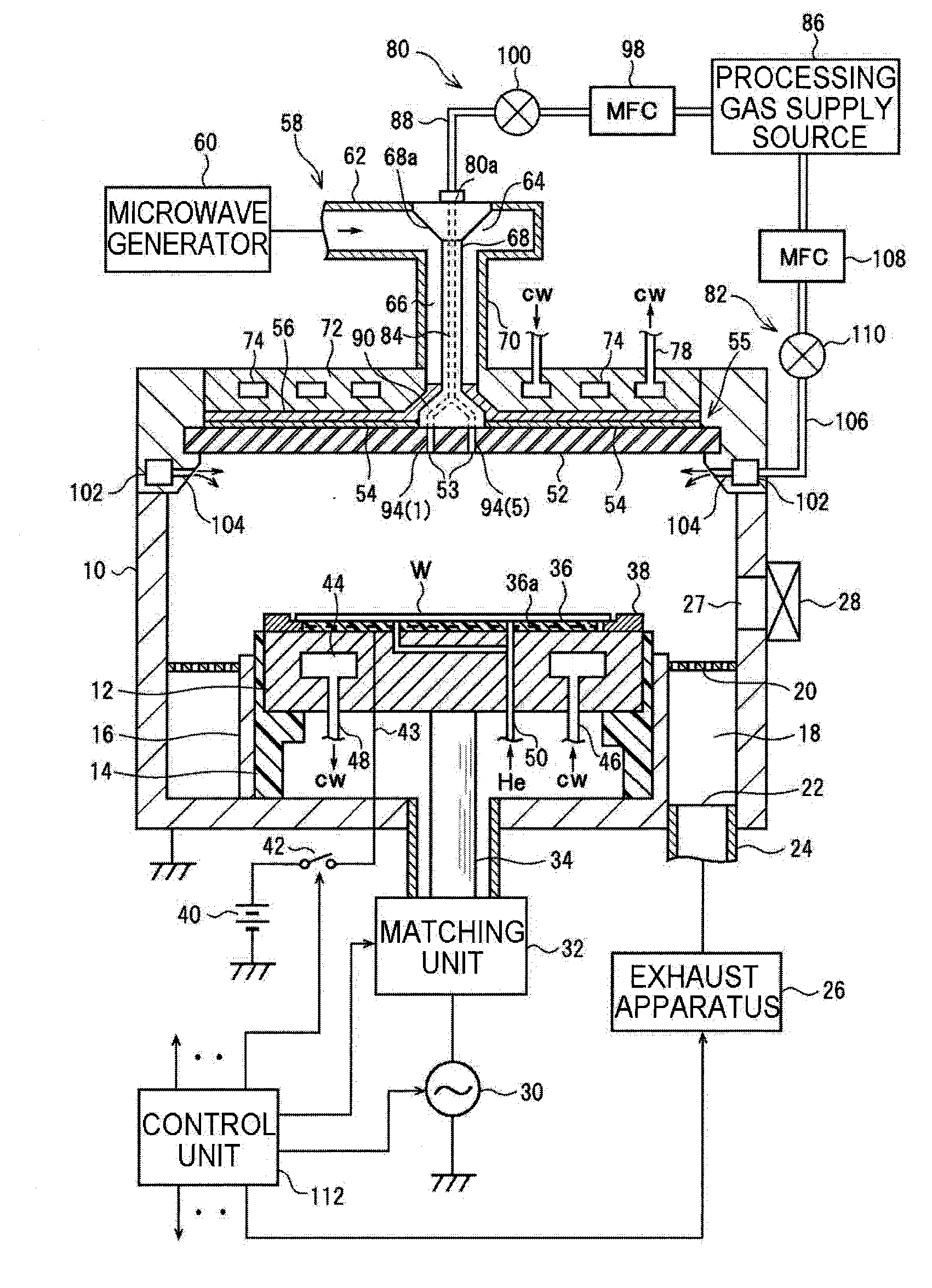
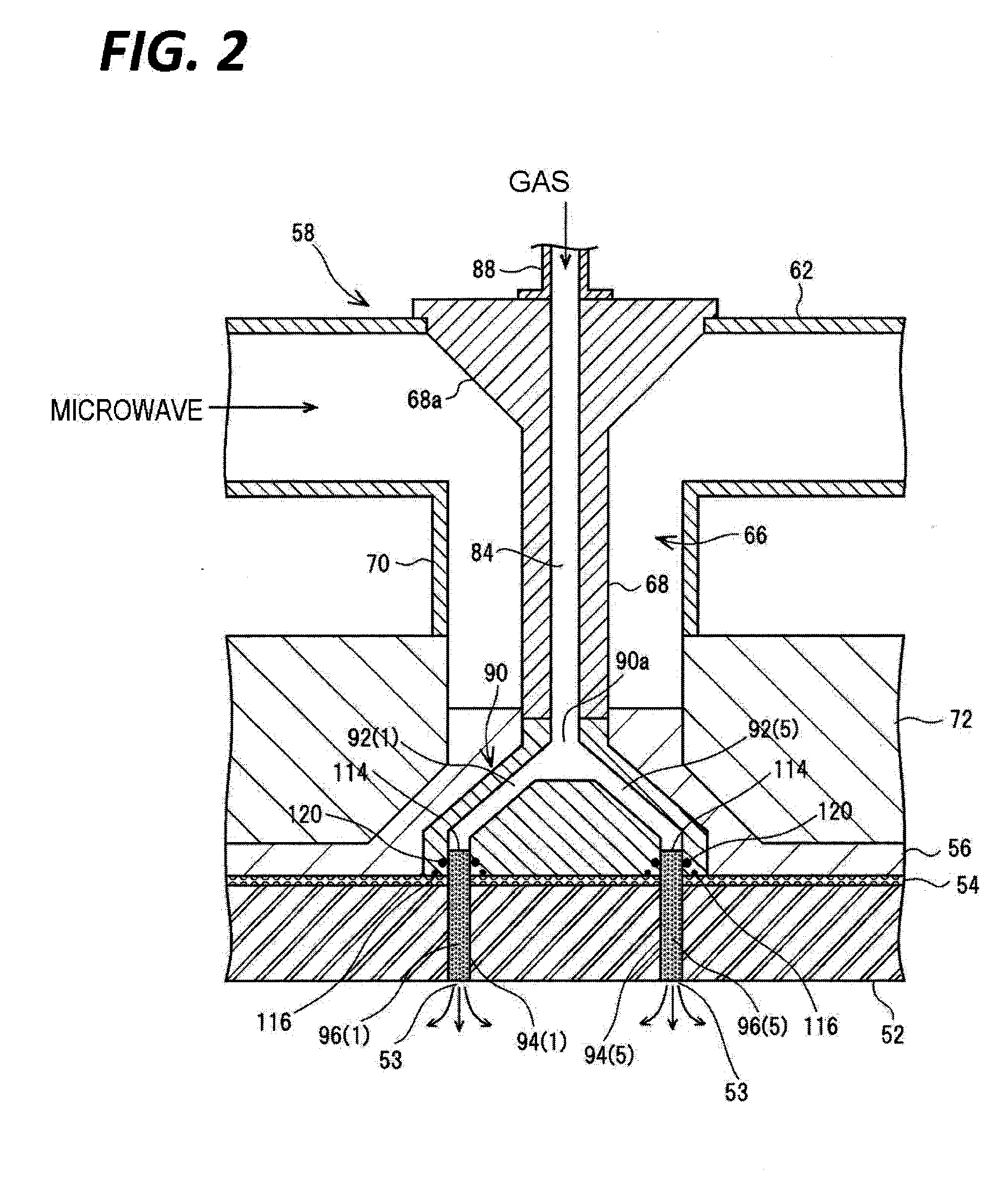
[0112]FIG. 4 illustrates a configuration around a dielectric window gas flow path in Example 1. As illustrated, in the present example, each electric discharge prevention member 96(n) provided in one of the dielectric window gas flow paths 94(n) forms a whole of (or a part of) the corresponding dielectric window gas flow path 94(n), and the inlet side portion 114 of the electric discharge prevention member 96(n) protrudes upward by a height h which is equal to or longer than a predetermined distance H from the rear surface of the dielectric window 52 and is inserted into a branched gas supply. path 92(n) of the connector unit 90 through an opening 54a in the slot plate 54.

[0113]Here, an endless or ring-shaped conductor that surrounds the electric discharge prevention member 96(n), for example, a spring coil 116, is inserted between the bottom surface of the connector unit 90 and the top surface of the slot plate 54. In t...

modified example of example 1

[0129]FIGS. 6A to 6H illustrate several modified examples in Example 1. In the modified example of FIG. 6A, a cylindrical conductor (collar) 132 extending upward from the rear surface of the dielectric window 52 to a position in the vicinity of the O-ring 120 is fitted on the outer circumferential surface of the protruding portion 114 of the electric discharge prevention member 96(n). In addition, an annular or endless flexible conductor, for example, a spring coil 134 is inserted between the outer circumferential surface of the conductor collar 132 and the inner circumferential surface of the connector unit (or the external gas tube) 90. Between the lower end of the connector unit (or the external gas tube) 90 and the top surface (rear surface) of the dielectric window 52, a gap 136 may occur due to, for example, an assembling error or thermal expansion of each member. In the present modified example, the surrounding conductor 118 is segmented into a plurality of conductor members ...

applied example of example 1

[0147]As illustrated in FIG. 10, a configuration, in which the inlet of the dielectric window gas flow path 94 is disposed on a side surface of the dielectric window 52 rather than on the rear surface (top surface) of the dielectric window 52, is also possible. Even in this case, a configuration, in which the electric discharge prevention member 96 provided in the dielectric window gas flow path 94 has a protruding portion 114 as described above and a surrounding conductor 118 which is the same as that described above surround the protruding portion 114, may be properly employed.


PUM

PropertyMeasurementUnit
Lengthaaaaaaaaaa
Lengthaaaaaaaaaa
Lengthaaaaaaaaaa

Abstract

This microwave plasma processing apparatus has, as a gas introduction mechanism for introducing a working gas inside a chamber (10), electrical discharge prevention members (96(1) to 96(8)), each of which is provided to a plurality of dielectric window gas passages (94(1) to (94(8)) through which a dielectric window (54) passes. Each electrical discharge prevention member (96(n)), a portion (114) of which protrudes only a height h, which is greater than or equal to a predetermined distance H, upward from the rear surface of a dielectric window (52) on the inlet side, passes through an opening (54a) of a slot plate (54), and inserts into a branched gas supply path (92(n)) of a gas branch part (90). The gas branch part (90), spring coils (116) and the slot plate (54), which surround the protruding portion (114) of each electrical discharge prevention member (96(n)), constitute an enclosing conductor (118).

Description

TECHNICAL FIELD[0001]The present disclosure relates to a plasma processing apparatus that performs a desired processing on a substrate to be processed using plasma generated by electromagnetic discharge of a processing gas.BACKGROUND[0002]In a manufacturing process of semiconductor devices or flat panel displays (FPDs), plasma is frequently used so as to cause a processing gas to conduct a good reaction at a relatively low temperature in a processing such as, for example, etching, deposition, oxidation, or sputtering. Conventionally, plasma generated by high frequency discharge in a MHz region or plasma generated by microwave discharge in a GHz region is widely used in such plasma processings.[0003]The plasma generated by the microwave discharge has an advantage in that low electron temperature and high density plasma may be generated under a low pressure. In particular, when a microwave introduction window structure incorporating a slot antenna is employed, there are advantages in ...

Claims


Application Information

Patent Timeline
IPC IPC(8): H01J37/32
CPCC23C16/45563C23C16/511H01J37/32192H05H2001/463H01J37/3244H01J37/32495H01J37/32201H01J37/321H05H1/463
Inventor ISHIBASHI, KIYOTAKAMORITA, OSAMU
Owner TOKYO ELECTRON LTD
Why Eureka
Try Eureka