Liquid ejecting head, liquid ejecting apparatus, piezoelectric element, and manufacturing method thereof

Active Publication Date: 2014-09-18
SEIKO EPSON CORP
View PDF5 Cites 19 Cited by
  • Summary
  • Abstract
  • Description
  • Claims
  • Application Information

AI Technical Summary

Benefits of technology

[0011]An advantage of some aspects of the invention is to provide a liquid ejecting head which suppresses peeling-off of an electrode or a wiring layer and s

Problems solved by technology

However, if an adhesion layer is patterned by wet etching, using the adhesion layer such as nickel chrome as the wiring layer, since acid is used as an etchant which is used when performing the wet etching of the adhesion layer, electric corrosion may occur in the electrodes due to the acid, and peeling-off of the electrode or peeling-off of the wiring layer may occur.
In addition, if acid is used when performing the wet etching of the adhesion layer, this acid may damage the piezoelec

Method used


Image

  • Liquid ejecting head, liquid ejecting apparatus, piezoelectric element, and manufacturing method thereof
  • Liquid ejecting head, liquid ejecting apparatus, piezoelectric element, and manufacturing method thereof
  • Liquid ejecting head, liquid ejecting apparatus, piezoelectric element, and manufacturing method thereof

Examples


embodiment 1

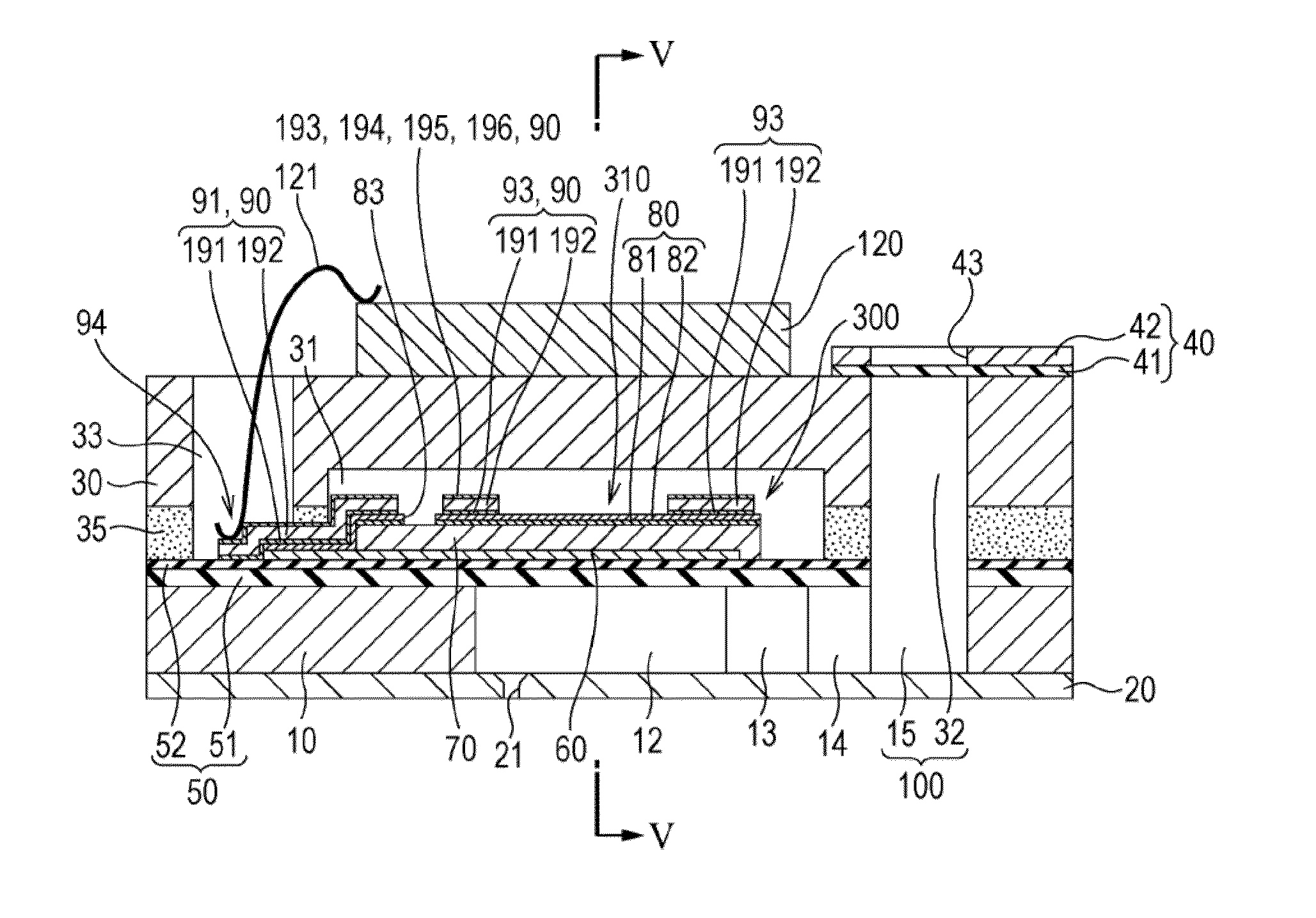
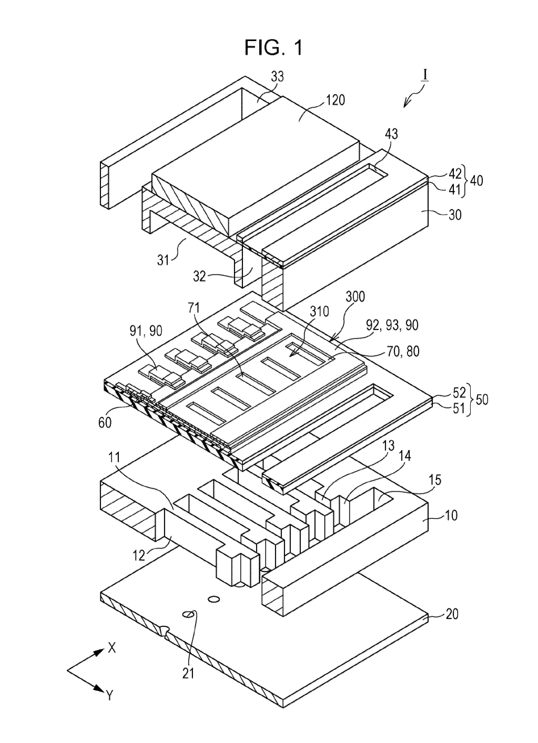
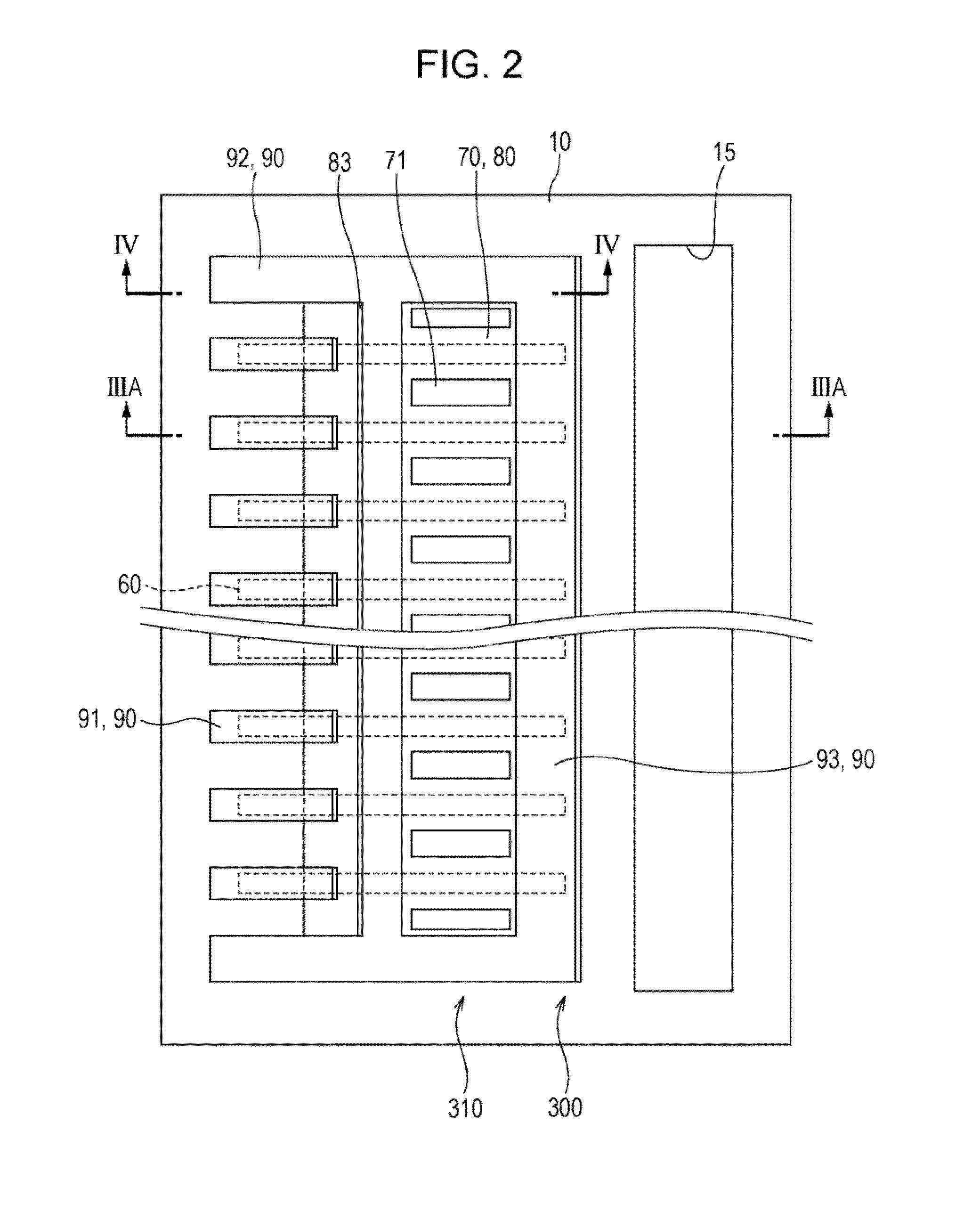
[0039]FIG. 1 is a perspective view of an ink jet type recording head which is an example of a liquid ejecting head according to Embodiment 1 of the invention, FIG. 2 is a plan view of a flow path formation substrate of the ink jet type recording head, FIGS. 3A and 3B are cross-sectional views taken along lines IIIA-IIIA and IIIB-IIIB, respectively, of FIG. 2, FIG. 4 is a cross-sectional view taken along line IV-IV of FIG. 2, and FIG. 5 is a cross-sectional view taken along line V-V of FIG. 3.

[0040]As shown in the drawings, pressure generation chambers 12 are formed on a flow path formation substrate 10 included in an ink jet type recording head I which is an example of the liquid ejecting head of the embodiment. The pressure generation chambers 12 which are partitioned by a plurality of partition walls 11 are provided in a line along a direction in which a plurality of nozzle openings 21 ejecting the same color of ink are provided in a line. Hereinafter, this direction is referred t...

example

[0117]Herein, in the same manner as in Embodiment 1 described above, the adhesion layer 191 formed of titanium tungsten (TiW) and the conductive layer 192 formed of copper (Cu) are laminated to each other and the conductive layer 192 is patterned, and then the etching of the adhesion layer 191 is performed with the etching solution containing hydrogen peroxide water, ammonia filtered water, and an alkaline component to form the lead electrode 90 of the example.

embodiment 2

[0131]FIGS. 13A and 13B are respectively an enlarged cross-sectional view and a cross-sectional view taken along line XIIIB-XIIIB of a main portion of an ink jet type recording head which is an example of a liquid ejecting head of Embodiment 2 of the invention. The members same as those in Embodiment 1 described above are denoted with the same reference numerals and the overlapping description thereof will be omitted.

[0132]As shown in the drawings, in the piezoelectric element 300 loaded on the ink jet type recording head I of the embodiment, the first electrode 60 is a common electrode which is continuously provided over the plurality of active portions 310 and the second electrode 80 is an individual electrode which is separately provided on each active portion 310.

[0133]In detail, the first electrode 60 is provided to have a narrower width than the width of the pressure generation chamber 12 in the second direction Y, and is continuously provided along the first direction X.

[0134...


PUM


Abstract

There is provided a liquid ejecting head including: a flow path formation substrate on which a pressure generation chamber communicating with nozzle openings for discharging liquid is provided; and a piezoelectric element which is provided on the flow path formation substrate and includes a piezoelectric layer, an electrode, and a wiring layer connected to the electrode, in which the wiring layer includes an adhesion layer which is provided on the electrode side and contains at least titanium and tungsten, and a conductive layer containing copper which is provided on a side of the adhesion layer opposite the electrode.

Description

BACKGROUND[0001]1. Technical Field[0002]The present invention relates to a liquid ejecting head which ejects liquid from nozzle openings, a liquid ejecting apparatus which includes the liquid ejecting head, a piezoelectric element which is loaded on the liquid ejecting head, and a manufacturing method thereof.[0003]2. Related Art[0004]There is known a liquid ejecting head which ejects liquid droplets from nozzle openings communicating with a pressure generation chamber, by deforming a piezoelectric element (piezoelectric actuator) to generate pressure fluctuation in the liquid in the pressure generation chamber. As a representative example of this liquid ejecting head, there is an ink jet type recording head which ejects ink droplets as the liquid droplets.[0005]The ink jet type recording head, for example, includes a piezoelectric element on one surface side of a flow path formation substrate on which a pressure generation chamber communicating with nozzle openings is provided, and...

Claims


Application Information

Patent Timeline
IPC IPC(8): B41J2/14C23C28/02C23C18/54H01L41/047H01L41/09
CPCB41J2/14201C23C18/54H01L41/09H01L41/0475C23C28/023C23C18/1651B41J2/055B41J2/14233B41J2/161B41J2/1623B41J2/1628B41J2/1629B41J2/1631B41J2/1642B41J2/1645B41J2/1646B41J2002/14241B41J2002/14491H10N30/875H10N30/1051H10N30/2047
Inventor FURUYA, NOBORU
Owner SEIKO EPSON CORP
Why Eureka
Try Eureka