Eureka AIR delivers breakthrough ideas for toughest innovation challenges, trusted by R&D personnel around the world.

Terminal, Method of Manufacturing Terminal, and Termination Connection Structure of Electric Wire

a technology of termination connection and manufacturing terminal, which is applied in the direction of manufacturing tools, contact member manufacturing, and capacitors, etc., can solve the problems of inability to avoid the influence of product life, poor contact, and progress of galvanic corrosion, so as to reduce the oxidation and corrosion of metals, reduce the cracking and springback after crimping the tubular crimp portion, and increase the durability

Active Publication Date: 2014-09-18
FURUKAWA ELECTRIC CO LTD +1
View PDF8 Cites 30 Cited by
  • Summary
  • Abstract
  • Description
  • Claims
  • Application Information

AI Technical Summary

Benefits of technology

The present disclosure provides a terminal with improved anticorrosion properties and durability, preventing cracking during crimp connecting and springback after crimping. The terminal has an annealed portion that prevents cracking and improves durability and reliability. The crimp portion of the terminal is welded in a way that prevents cracking and improves durability and reliability. The terminal and the termination connection structure of the electric wire prevent moisture and oxidation from affecting the contact points between the electric wire and the terminal, ensuring reliability and durability of the wire harness. The method of manufacturing the terminal simultaneously forms the annealed portion and the tubular crimp portion, reducing production costs. The present disclosure provides a solution to the problem of cracking and springback after crimping of the tubular crimp portion and improves the durability and reliability of the terminal.

Problems solved by technology

When metals used for the electric wire and the terminal are different from each other, galvanic corrosion progresses.
Progression of metal oxidation and corrosion at the connecting part causes a crack and a poor contact at the connecting part, and an influence on a product life cannot be avoided.
Particularly, in recent years, wire harnesses having an electric wire made of an aluminum alloy and a terminal base material made of a copper alloy are put to practical use, and thus problems of oxidation and corrosion of the connection part are becoming more prominent.
However, in a case where an aluminum alloy is used for the terminal, strength and spring characteristics of the terminal per se are not sufficient.
Further, in order to compensate for the above, a structure incorporating a spring made of an iron-based material in the terminal is employed, and thus there is a problem of galvanic corrosion between a spring member and a terminal base material (aluminum) and a problem of an increased production cost due to time and efforts required for assembling.
However, there is a problem of an increased volume of a crimp portion due to an existence of the cap and a problem of a bad crimp connection and an increased production cost due to an increase in number of parts.
Further, in Japanese Laid-Open Patent Publication No. 2011-222243, a method of molding an entire crimp connection portion with a resin is employed, and there is a problem of an increased size of a connector housing due to an enlarged mold portion, which makes it difficult to make the entire wire harness with a high-density and miniaturized structure, and a problem that a process of manufacturing a wire harness and an operation thereof become more complicated.
However, there is a problem that a process of attaching the aforementioned metal cap to each conductor before crimping the crimp piece of the terminal metal fitting is cumbersome and a problem of an immersion due to breakage of the metal cap by a wire barrel during crimping.
Further, how to maintain strength of a connecting part between the electric wire and the terminal and to increase durability and reliability thereof, while preventing the connecting part from having an increased size as well as preventing a complicated connecting process and an increased cost, is problematic.
This not only causes a contact failure between the electric wire and the terminal but also allows intrusion of moisture into the gap, and may cause corrosion.

Method used


Image

  • Terminal, Method of Manufacturing Terminal, and Termination Connection Structure of Electric Wire
  • Terminal, Method of Manufacturing Terminal, and Termination Connection Structure of Electric Wire
  • Terminal, Method of Manufacturing Terminal, and Termination Connection Structure of Electric Wire

Examples


examples

[0065]Hereinafter, test results and evaluation results of the present disclosure will be shown. Note that the present disclosure is not limited to examples related to the following tests.

[0066]A first example will be described. In the first example, a copper alloy board FAS-680 (thickness 0.25 mm, H material) manufactured by Furukawa Electric Co., Ltd. was used as the metal base material of the terminal. FAS-680 is an alloy having a composition containing 2.0 to 2.8 mass % nickel (Ni), 0.45 to 0.6 mass % silicon (Si), 0.4 to 0.55 mass % zinc (Zn), 0.1 to 0.25 mass % tin (Sn), 0.05 to 0.2 mass % magnesium (Mg), and the balance is copper (Cu) and incidental impurities. FAS-680 has a Vickers hardness of approximately 200 Hv. At least at a part of the metal base material in which the weld portion was formed, a metal member on which a tin plating was applied was used as a plating portion.

[0067]The core wire of the aluminum wire was an aluminum alloy MSAl (wire, wire size 0.43 mm) manufac...


PUM

PropertyMeasurementUnit
thicknessaaaaaaaaaa
temperatureaaaaaaaaaa
output poweraaaaaaaaaa

Abstract

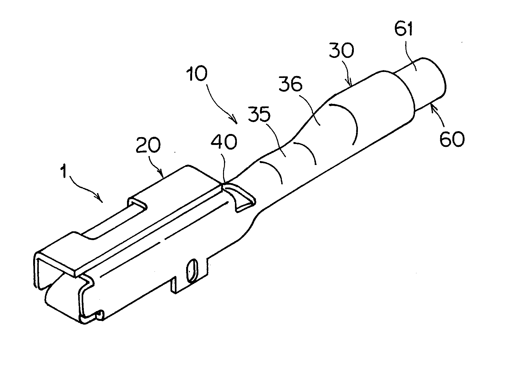
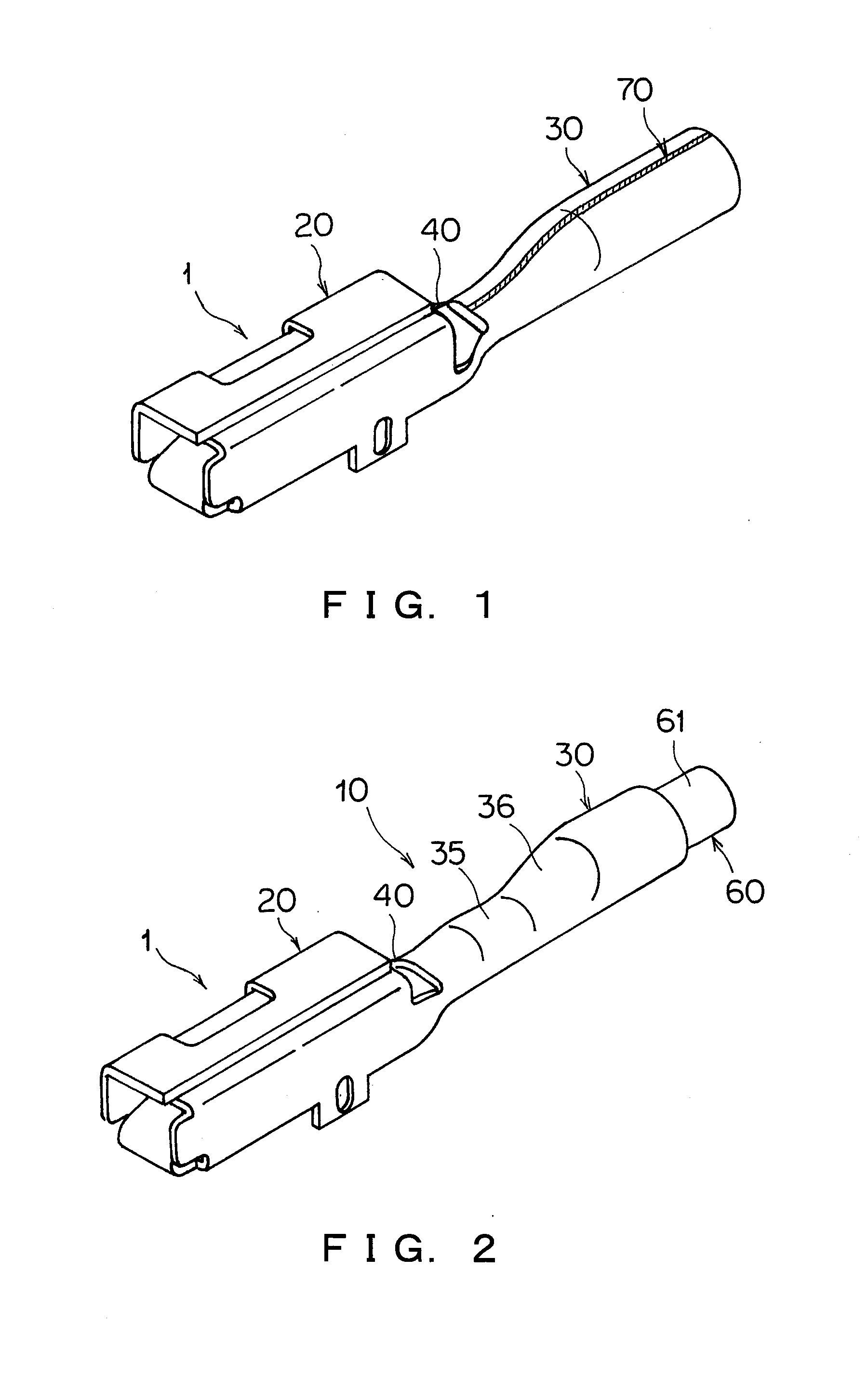
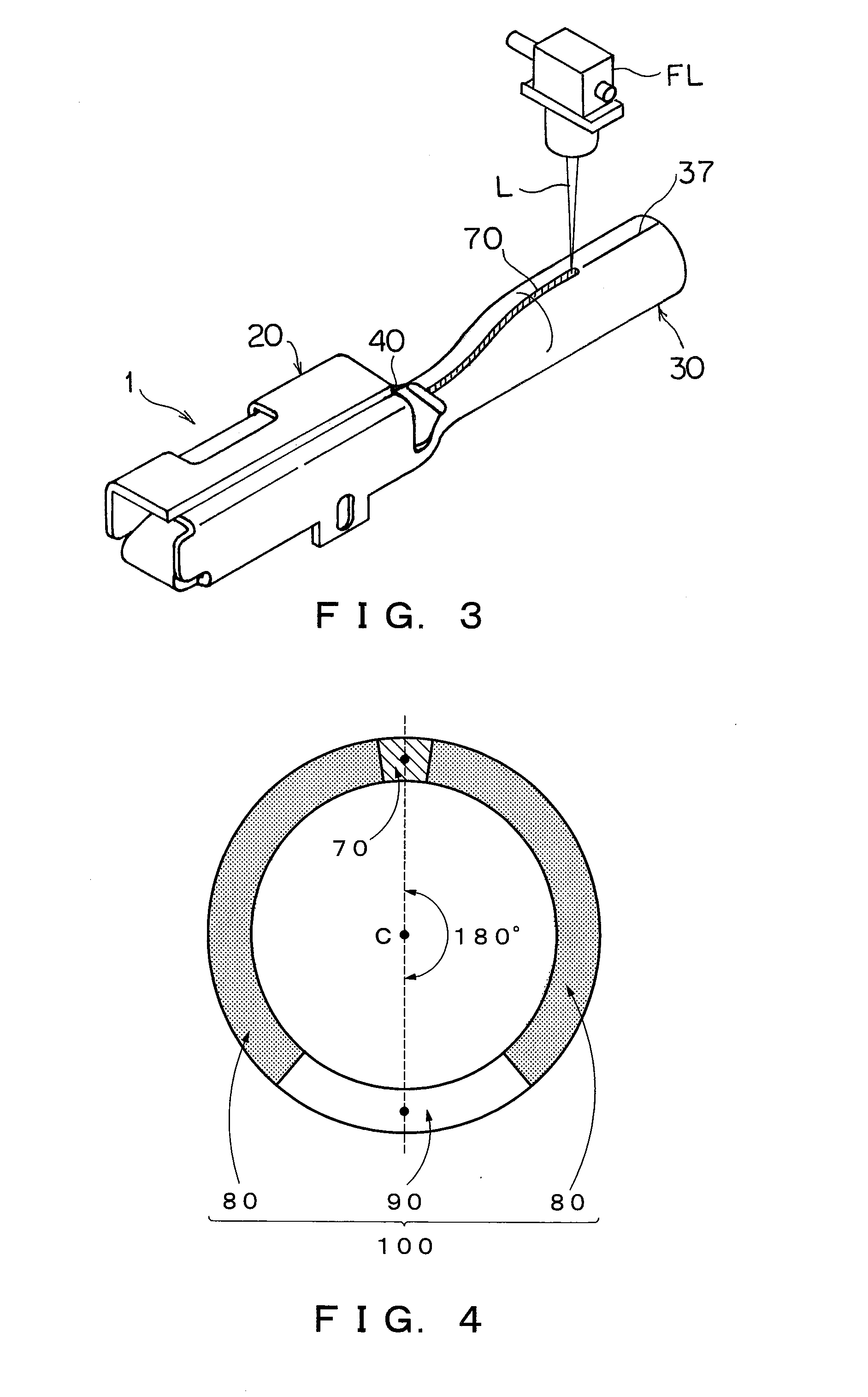
A terminal includes a tubular crimp portion that crimp connects with an electric wire. The tubular crimp portion is composed of a metal member. The tubular crimp portion includes a non-weld portion and a weld portion, the weld portion being formed by welding. A metal base material constituting the metal member of the non-weld portion includes a normal portion and an annealed portion.

Description

CROSS REFERENCE TO RELATED APPLICATIONS[0001]This is a continuation application of International Patent Application No. PCT / JP2013 / 070523 filed Jul. 29, 2013, which claims the benefit of Japanese Patent Application Nos. 2012-167779, 2013-034022 and 2013-034023, filed Jul. 27, 2012, Feb. 23, 2013 and Feb. 23, 2013, respectively, the full contents of all of which are hereby incorporated by reference in their entirety.BACKGROUND[0002]1. Technical Field[0003]The present disclosure relates to a terminal with a reduced possibility of cracking during crimping and springback after crimping as well as an improved anticorrosion property, a method of manufacturing thereof, and a termination connection structure of an electric wire.[0004]2. Background Art[0005]In the related art, a connection between an electric wire and a terminal in an automotive wire harness or the like is generally a crimp connection in which an electric wire is crimped with a terminal which is referred to an open barrel ty...

Claims


Application Information

Patent Timeline
Patent Type & Authority Applications(United States)
IPC IPC(8): H01R4/18H01R43/02H01R4/20
CPCH01R43/048H01R43/16H01R43/02H01R4/187H01R4/20H01R4/184B23K26/32Y10T29/49213B23K2101/38B23K2103/10B23K2103/12C22F1/08B23K26/21H01R4/183H01R43/0221
Inventor TACHIBANA, AKIRAMITOSE, KENGOYAGI, SABURO
Owner FURUKAWA ELECTRIC CO LTD
Why Eureka
Eureka Blog
Learn More