
Device and method for determining vital signs of a subject

Active Publication Date: 2014-09-18
KONINKLJIJKE PHILIPS NV
View PDF1 Cites 39 Cited by
  • Summary
  • Abstract
  • Description
  • Claims
  • Application Information

AI Technical Summary

Benefits of technology

The present invention aims to provide an improved device and method for detecting vital signs of a person with increased accuracy and efficiency in reduction of facial motion-related artifacts. The invention uses an analyzer to determine the spatial and temporal properties of the skin area used for extracting the desired vital sign signal, such as smoothness and consistency, and adjusts the parameters and algorithm used for extraction and post-processing accordingly. The invention also utilizes reliability information, such as the reliability of the determination of the vital sign information or the relative importance of different parts of the skin area, to improve the accuracy of the desired vital sign. The invention can adapt the post-processing based on the determined properties of the skin area and can update the vital sign only if the reliability information indicates a reliability threshold. Overall, the invention enhances the accuracy and efficiency of detecting vital signs.

Problems solved by technology

Although contact PPG is regarded as a basically non-invasive technique, contact PPG measurement is often experienced as being unpleasant, since the pulse oximeter is directly attached to the subject and any cables limit the freedom to move.
Therefore, remote photoplethysmographic systems and devices are considered unobtrusive and well suited for medical as well as non-medical everyday applications.
However, remote PPG devices typically achieve a lower signal-to-noise ratio.
There still are demanding situations, with severe motion, challenging environmental illumination conditions, or high required accuracy of the application, where an improved robustness of the remote PPG devices and methods are required.

Method used


Image

  • Device and method for determining vital signs of a subject
  • Device and method for determining vital signs of a subject
  • Device and method for determining vital signs of a subject

Examples


Embodiment Construction

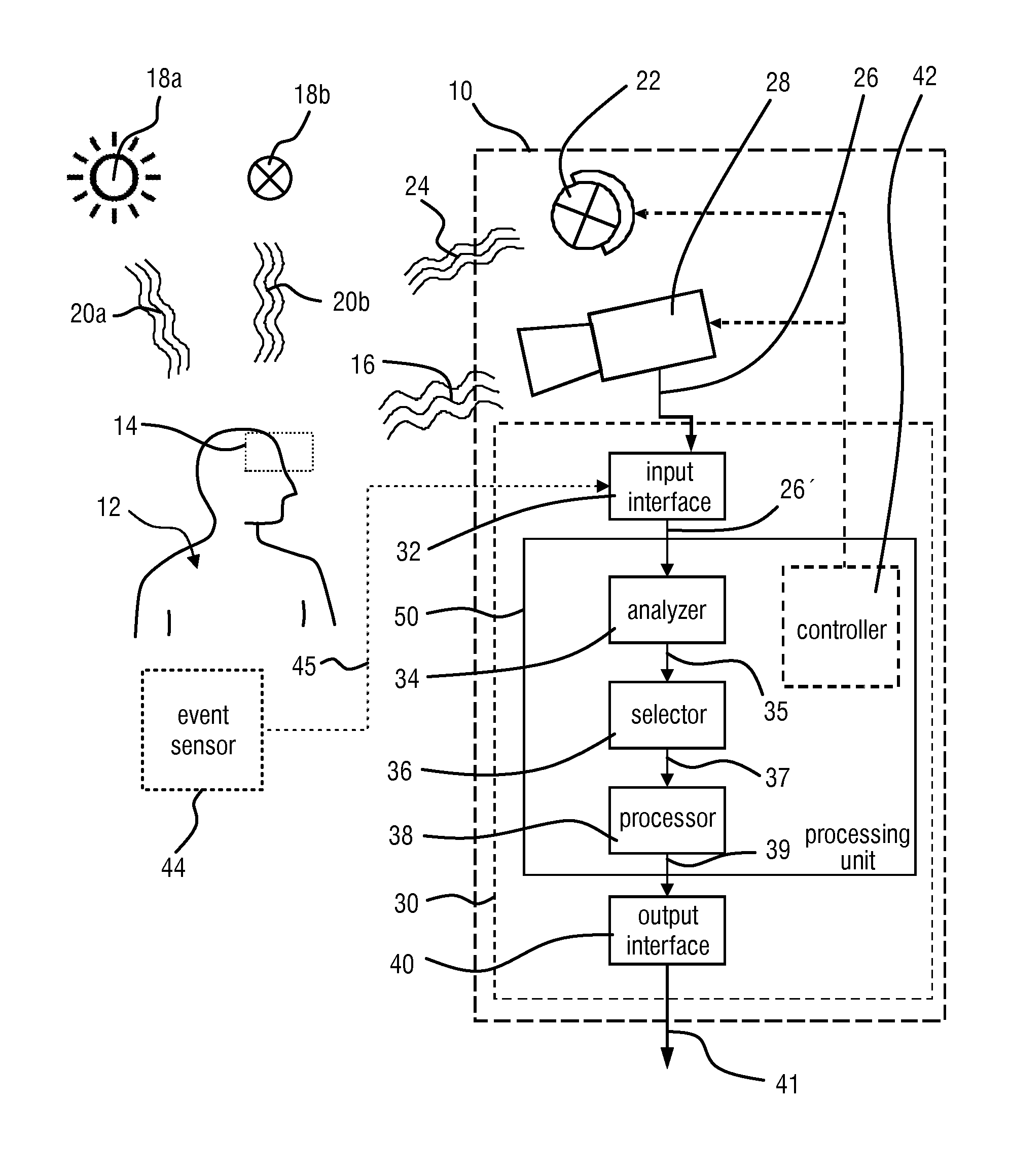
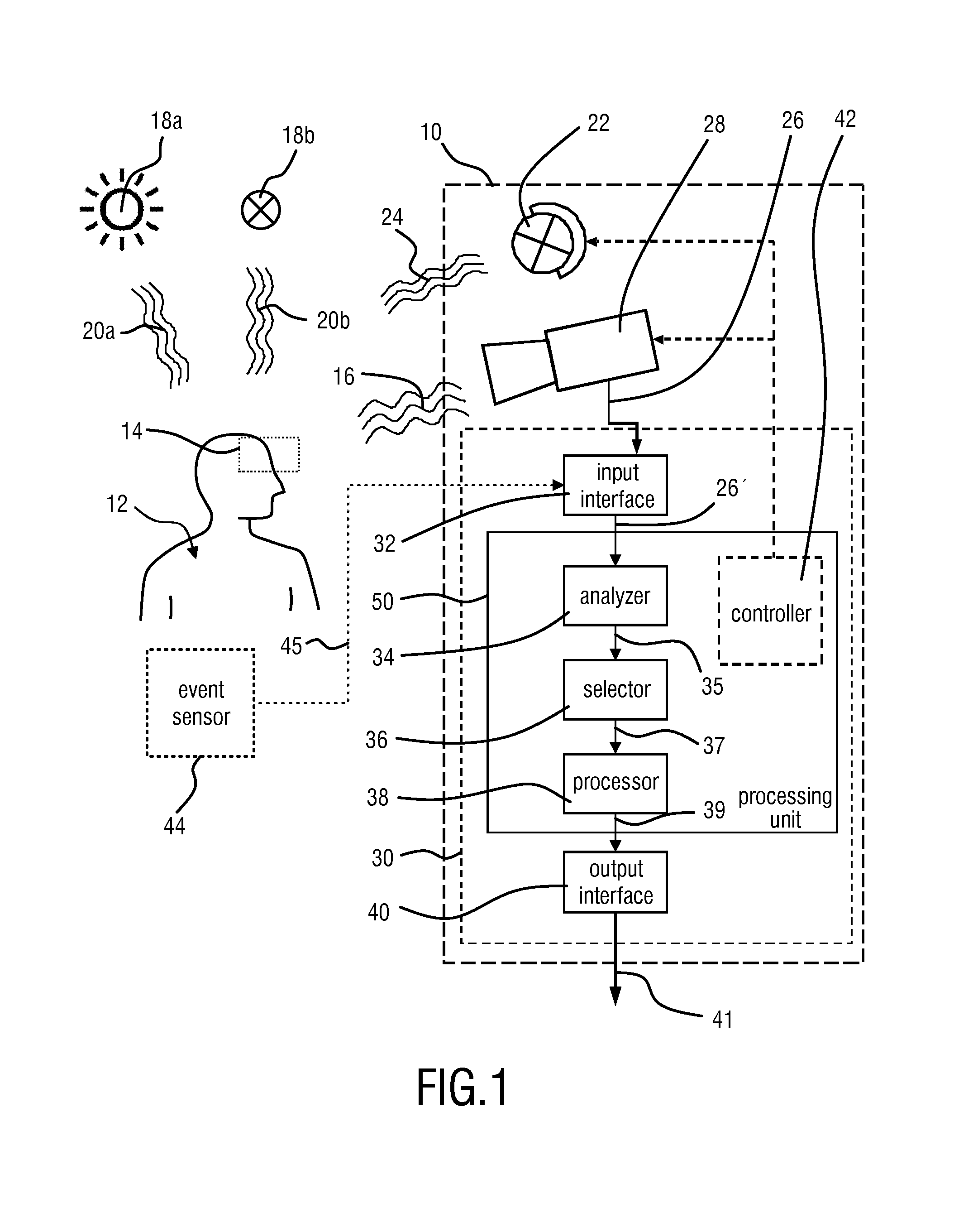
[0043]FIG. 1 shows a schematic diagram of a system 10 in which a device 30 according to the present invention is used. The system 10 can be utilized for recording image frames representing a remote subject 12 or at least a portion 14 (a region of interest) of the subject 12 for remote PPG monitoring. The region of interest 14 comprises, by way of example, a forehead portion, a face portion or, more generally, one or more skin portions of the subject 12. The recorded data, for instance, a series of image frames, can be derived from electromagnetic radiation 16 reflected by the subject 12. Possibly, under certain conditions, at least part of the electromagnetic radiation could be emitted or transmitted by the subject 12 itself Radiation transmission may occur when the subject 12 is exposed to strong illumination sources shining through the subject 12. Radiation emission may occur when infrared radiation caused by body heat is addressed and captured. However, for remote PPG application...


PUM


Abstract

A device for determining a vital sign of a subject comprises an interface that receives a data stream derived from detected electromagnetic radiation reflected from a region of interest including a skin area of the subject, said data stream comprising a data signal per skin pixel area of one or more skin pixels for a plurality of skin pixel areas of said region of interest, a data signal representing the detected electromagnetic radiation reflected from the respective skin pixel area over time. An analyzer analyzes spatial and / or temporal properties of the skin area. A processor determines a vital sign information signal of the subject based on the data signals of skin pixel areas within the skin area, and a post-processor determines the desired vital sign from said vital sign information signal, wherein said determined spatial and / or temporal properties are used by the processor for determining the vital sign information signal and / or by the post-processor for determining the desired vital sign.

Description

CROSS REFERENCE TO RELATED APPLICATIONS[0001]This application claims the benefit of U.S. provisional application Ser. No. 61 / 781,269 filed Mar. 14, 2013 and European provisional application serial no. 13159173.7 filed Mar. 14, 2013, both of which are incorporated herein by reference.FIELD OF THE INVENTION[0002]The present invention relates to a device and a method for determining the vital signs of a subject. In particular, the present invention relates to an unobtrusive optical measurement approach which can be used for detecting vital signs in an observed subject, such as a person or animal. In this context, optical measurement refers to remote photoplethysmography (R-PPG).BACKGROUND OF THE INVENTION[0003]Vital signs of a person, for example the heart rate (HR), the respiration rate (RR) or the blood oxygen saturation, serve as indicators of the current state of a person and as powerful predictors of serious medical events. For this reason, vital signs are extensively monitored in...

Claims


Application Information

Patent Timeline
IPC IPC(8): A61B5/024A61B5/00
CPCA61B5/7235A61B5/02416A61B5/0077A61B5/7221A61B5/725G06T7/0016G06T2207/10016G06T2207/10024G06T2207/20021G06T2207/30076
Inventor KIRENKO, IHOR OLEHOVYCHDEN BRINKER, ALBERTUS CORNELIS
Owner KONINKLJIJKE PHILIPS NV
Learn More