Nonradioactive ionization source driver

a technology of nonradioactive ionization and source driver, which is applied in the direction of separation process, particle separator tube details, instruments, etc., can solve the problems of electric erosion and gas contamination

Inactive Publication Date: 2014-10-02
PEN
View PDF4 Cites 32 Cited by
  • Summary
  • Abstract
  • Description
  • Claims
  • Application Information

AI Technical Summary

Problems solved by technology

However, in this configuration, one of the electrodes is exposed to the ga

Method used


Image

  • Nonradioactive ionization source driver
  • Nonradioactive ionization source driver
  • Nonradioactive ionization source driver

Examples


Embodiment Construction

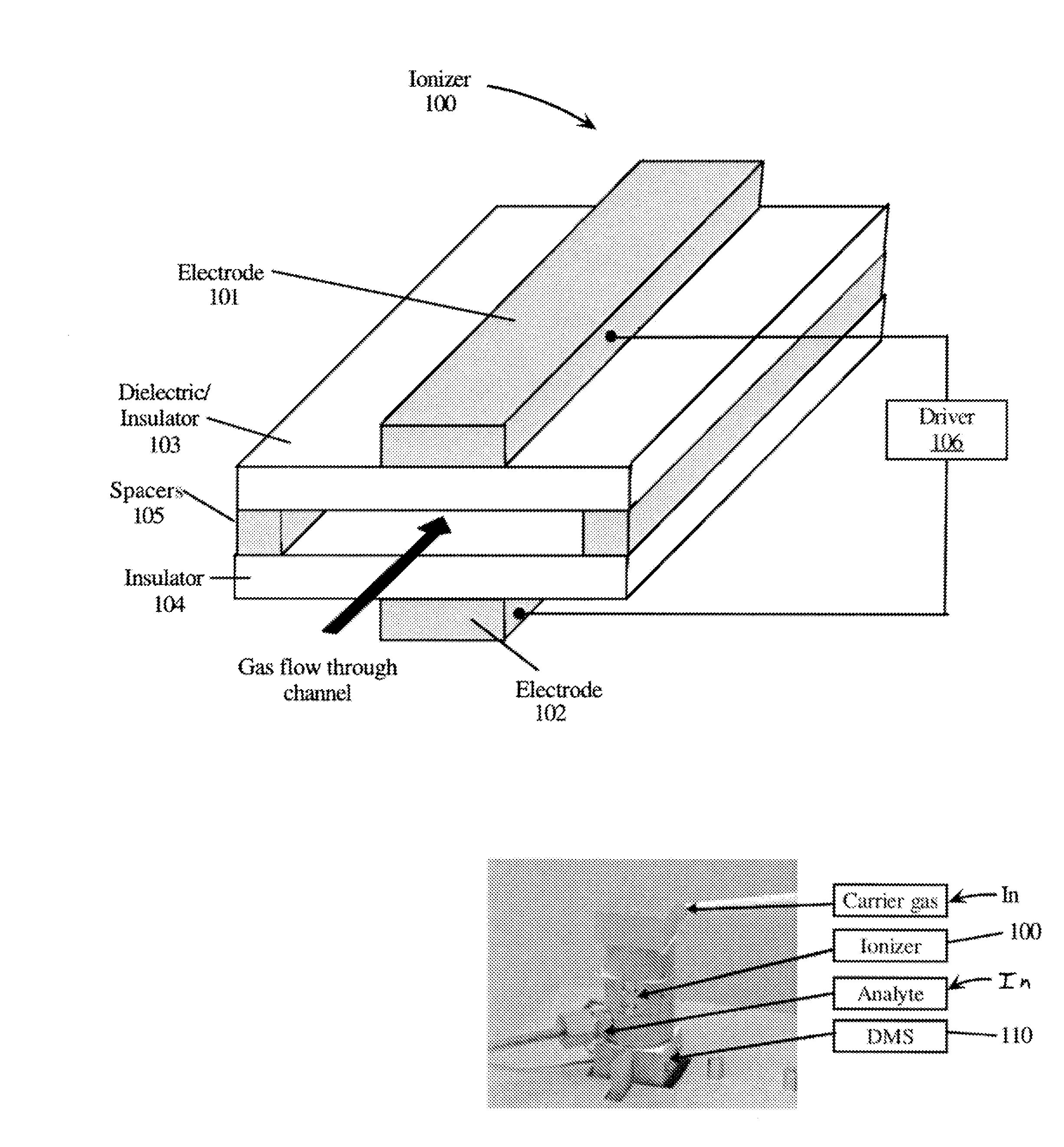
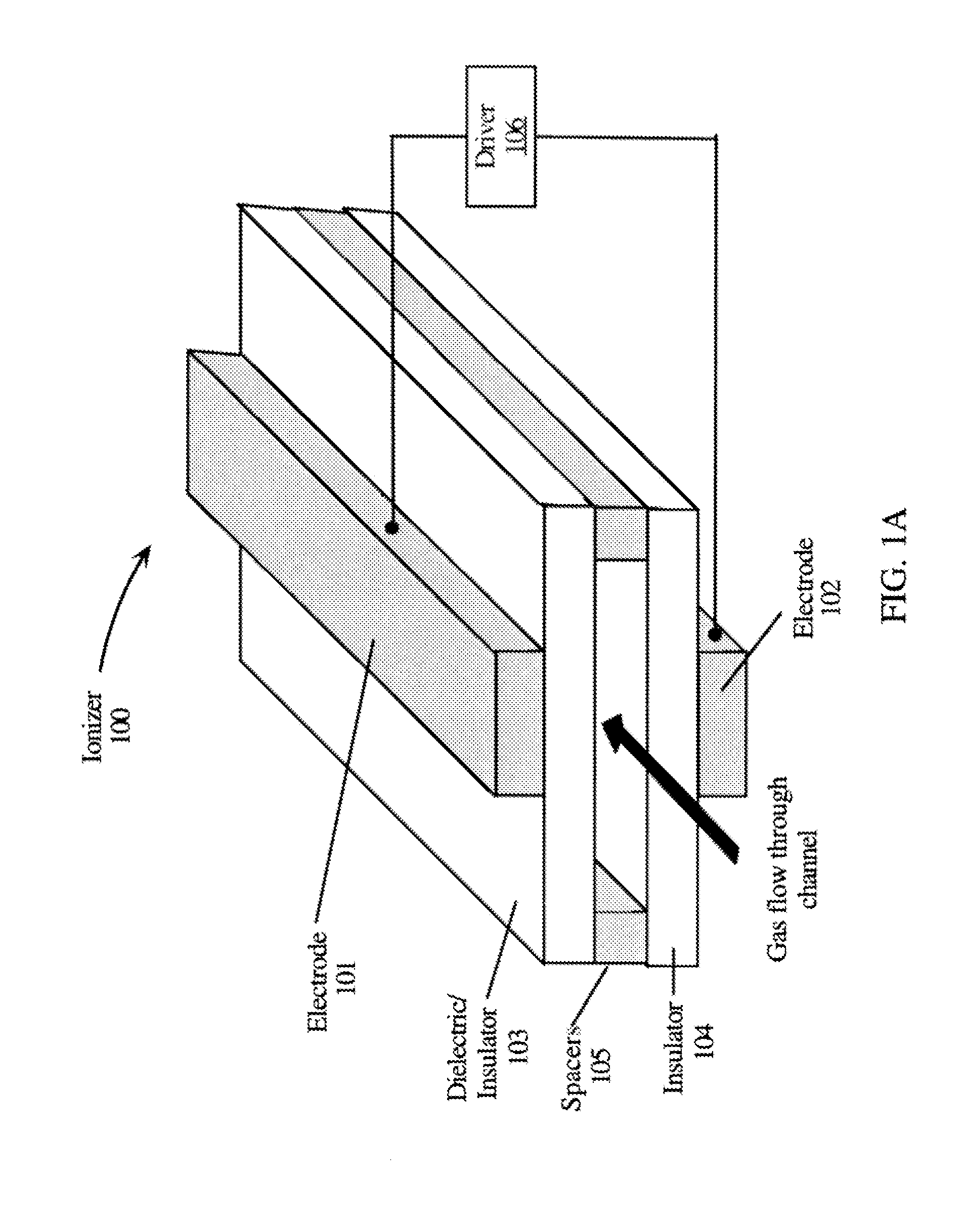
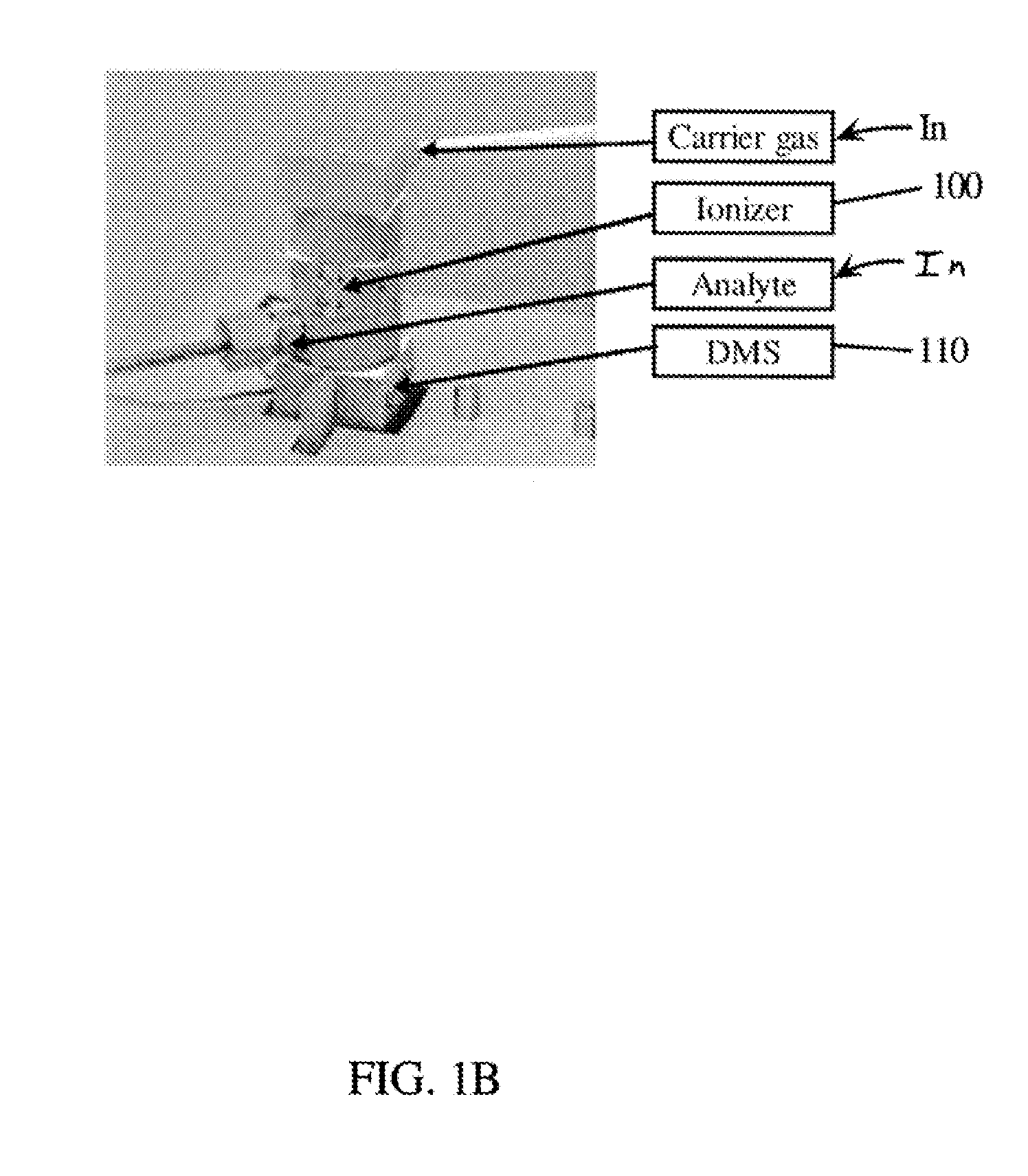
[0013]Embodiments of the present invention provide a nonradioactive ionization source that exhibits stability, low power consumption, and long lifetime to replace radioactive sources. The nonradioactive ionization source may be used in place of radioactive sources for instruments such as a differential mobility spectroscopy (“DMS”) analyzer and other ion mobility spectrometers (“IMS”), such as a time of flight ion mobility spectrometer and field asymmetric ion mobility spectrometers. As illustrated in FIG. 6, a principal of operation of such a DMS has volatile organic compound (“VOC”) analyte molecules ionized as they enter the DMS. The DMS is essentially an ion filter operating in a gas environment. In embodiments of the present invention, the gas environment is filtered and dried (de-humidified) air at near atmospheric pressure. As previously noted, the most common technique used to create gas ions is to place a radioactive source material (either beta emitter or alpha emitter) ne...


PUM


Abstract

System and method for operating an ionizer using a combination of amplitude modulation and pulse width modulation to control the plasma temperature and the type of ions needed for analytic equipment. Ion density can be controlled by the repetition rate. The ionizer may utilize a non-radioactive ionization source, and be coupled to a differential mobility spectroscopy (DMS) analyzer.

Description

This application claims priority to U.S. Provisional Patent Applications Ser. Nos. 61 / 587,352 and 61 / 618.947, which are hereby incorporated by reference herein.TECHNICAL FIELD[0001]The present invention relates in general to utilization of gas ionization for detection of chemical compounds, such as in air.BACKGROUND INFORMATION[0002]Ion Mobility Spectrometry (“IMS”) for the detection of chemical warfare agents (“CWAs”), toxic industrial chemicals (“TICs”), drugs, and explosives is primarily based on gas ionization by radioactive sources (e.g., 63Ni, 241Am, and 3H), since these sources meet requirements of a portable device for field use: small sized and lightweight, good mechanical stability, and do not require any additional power. Furthermore, they are very reliable while displaying a good sensitivity with regard to the detection of quite a large number of compounds of interest. However, for well-known reasons (e.g., radiation safety, regulation, record keeping, disposal problems)...

Claims


Application Information

Patent Timeline
IPC IPC(8): H01J49/10H01J49/02
CPCB01D59/44H05H1/2406H05H2001/2412H01J49/10G01N27/624H05H1/24H01J49/022H05H2245/121H05H2245/15
Inventor TIKHONSKI, ALEXEITHUESEN, LEIF
Owner PEN
Why Eureka
Try Eureka