Method of detecting recirculation in an arteriovenous shunt during ongoing hemodialysis and dialysis system

a technology of arteriovenous shunt and shunt, which is applied in the direction of suction device, other medical device, medical device, etc., can solve the problems of deteriorating dialysis efficiency and general condition of patient, according to the state of the ar

Active Publication Date: 2014-10-02
B BRAUN AVITUM
View PDF0 Cites 6 Cited by
  • Summary
  • Abstract
  • Description
  • Claims
  • Application Information

AI Technical Summary

Benefits of technology

[0055]With the aid of the present invention it is possible to perform measurement for determining the recirculation in the shunt without influ

Problems solved by technology

During dialysis therefore a too low shunt flow and hereby even a so called “recirculation” in the shunt may occur due to the afore-mentioned shunt complications.
Since recirculation is resulting in deterioration of the dialysis efficiency and, thus, the patient does not reach his/her objective of treatment, his/her general condition will deteriorate in the long run when unnoticed recirculation is provided.
Recirculation can result from two different reasons: An error in connecting the patient to the dialyser or, as explained, a degeneration of the shunt.
Although all afore-mentioned methods basically allow information as to quality and quantity of the recirculation in the vascular access of the dialysis patient, the methods according to the state of the art have a number of drawbacks, however:
The temperature dilution method is susceptible t

Method used


Image

  • Method of detecting recirculation in an arteriovenous shunt during ongoing hemodialysis and dialysis system
  • Method of detecting recirculation in an arteriovenous shunt during ongoing hemodialysis and dialysis system
  • Method of detecting recirculation in an arteriovenous shunt during ongoing hemodialysis and dialysis system

Examples


Embodiment Construction

[0088]It is the target of this invention to enable measurement without a bolus administration. In parallel to this, no additional technical equipment shall be necessary and thus the invention shall be based on a sensor system which is already provided (anyway) in a generic dialysis apparatus.

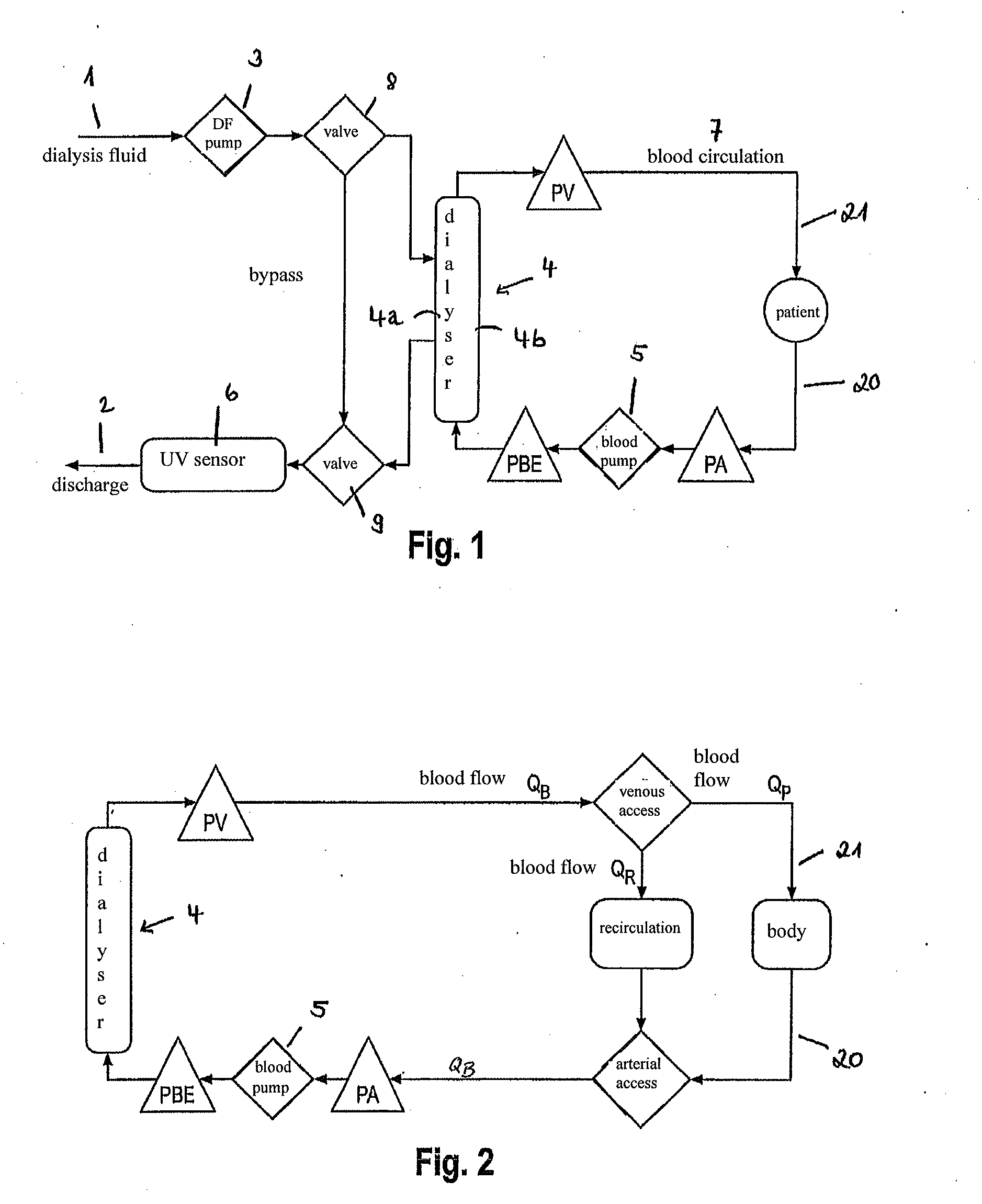
[0089]In the flow diagram of FIG. 1 a dialysis system according to aspects of the invention having a side facing away from the patient (dialysis fluid side) and a side facing the patient (blood side) is shown in schematic representation.

[0090]By 1 a dialysis fluid inlet is denoted and by 2 a dialysis fluid discharge is denoted. Via a flow pump 3 dialysis fluid is pumped into a dialysis fluid chamber 4a of a dialyser 4 so that the dialysis fluid flows through the chamber 4a in a predetermined direction. The dialyser 4 includes a semipermeable membrane not shown in FIG. 1 which forms the boundary between the distal side and the proximal side of the dialyser 4. Furthermore the dialyser 4 has a bloo...


PUM


Abstract

Control methods of a dialysis machine for allowing the dialysate-side detection of a recirculation in an arteriovenous shunt of a patient during ongoing hemodialysis are described. A sensor is arranged downstream of a dialyser and detects a change of a physicochemical parameter PD of outflowing dialysis fluid. Control elements are provided to guide the dialysis fluid in a selected manner through the dialyser or pass it by. Recirculation may be determined by passing the dialysis fluid by the dialyser so that the dialysis fluid is guided unchanged along the sensor for calibration, switching the control elements after optional sensor calibration such that the dialysis fluid flows through the dialyser, and adjusting a desired first blood flow value BF1 in the blood-side extracorporeal circulatory branch so that between an inlet of the extracorporeal circulatory branch and an outlet a recirculation R and, a first clearance K1 are adjusted and the parameter detected by the sensor adopts a corresponding value PD1, changing the first blood flow value BF1 to a second blood flow value BF2, wherein a second clearance K2 is adjusted, and accordingly at the sensor a new parameter value PD2 is provided and detected, and determining the recirculation R by the course of change from the parameter value PD1 to the parameter value PD2.

Description

CROSS REFERENCE TO RELATED APPLICATIONS[0001]This application claims priority to German application DE 10 2013 103 221.4 filed Mar. 28, 2013, the contents of such application being incorporated by reference herein.BACKGROUND OF THE INVENTION[0002]The present invention relates to a method of detecting recirculation in an arteriovenous shunt of a patient during ongoing hemodialysis.[0003]Patients suffering from severe kidney insufficiency or kidney failure require dialysis, as is known. For this, the patients concerned have two options of dialysis, on the one hand in a dialysis center of a hospital and, on the other hand, self-dialysis in the domestic area with ambulant dialysis units—after having been introduced by the nephrologist in charge and trained specialized staff—.[0004]For the purpose of the present invention, by the term “dialysis” or “hemodialysis” any chronically applicable blood purification therapy is understood which comprises hemodialysis, hemofiltration and hemodiafi...

Claims


Application Information

Patent Timeline
IPC IPC(8): A61M1/36
CPCA61M2205/3306A61M1/3658A61M1/1609A61M2205/3313A61M2205/3331A61M2205/3334A61M1/1615
Inventor KRAUSE, SILVIESTROHHOEFER, CHRISTOFAHRENS, JOERNCASTELLARNAU, ALEXWEYER, SOEREN
Owner B BRAUN AVITUM
Why Eureka
Try Eureka